
Manual


2
ENGLISH
Fast Ethernet Oce Switch • User Manual English
Thank you for purchasing the INTELLINET NETWORK SOLUTIONS
™
Fast Ethernet Office
Switch, Model 502023 (5-port plastic housing), Model 523301 (5-port metal housing),
Model 502054 (8-port plastic housing) or Model 523318 (8-port metal housing).
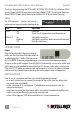
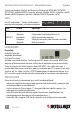
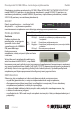
LEDs
The LED indicators — Power, Link/Activity —
make monitoring and troubleshooting easier.
CONNECTIONS
Power
Plug the female end of the power adapter
firmly into the IN jack and the other end into
an electrical outlet. Confirm that the power
LED is lit. NOTE: To ensure proper operation, use only the included power adapter.
All ports on the switch support Auto-MDI/MDI-X functionality, so crossover cables and
uplink ports are not needed for connections to PCs, routers, hubs, other switches, etc.
Cat5/5e UTP/STP cables provide optimal performance; if a status LED doesn’t indicate
a link or activity, check the corresponding device for proper setup and operation.
INSTALLATION
Prior to use, it is recommended that the switch be placed/positioned:
• onalevelsurfacethatcansupporttheweightoftheswitch(andanyotheritems
that need to be considered);
• withaminimumof25mm(approx.1”)ofclearanceonthetopandsidesfor
adequate ventilation;
• awayfromsourcesofelectricalnoise:radios,transmitters,broadbandampliers,etc.;
• whereitcannotbeaectedbyexcessivemoisture;and
• within100m(approx.328’)ofnetworkdevicesit’stobeconnectedto.
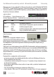
LED Status Operation
PWR On Power on
O ChecktheACconnection;turnthepoweron
LNK/ACT On Valid port connection
Blinking Valid port connection; data transmitted/received
O Nolinkestablished
PWR
LINK/ACT
1 2 543