Digital KVM over IP Switch quick install guide Models 503723 & 503730 Shown: 8-Port , Model 503723 INT-503723/503730-QIG-0808-01
introduction Thank you for purchasing the INTELLINET NETWORK SOLUTIONS™ Digital KVM over IP Switch, Model 503723 (8-Port) or Model 503730 (16-Port). This quick install guide presents the rudimentary steps required to set up and operate this device. For more detailed instructions and specifications, refer to the user manual 1) on the CD enclosed with this product; 2) on the Web site listed below; or 3) in some cases, printed and enclosed with this product.
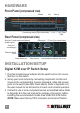
hardware Front Panel (compressed view) Selected Live Bank no. Port-switching buttons (8-port model shown) 10/100 Rear Panel (compressed view) Serial port 2 (serial power control/external modem support) Link Power Video Ethernet port PC ports (8-port model shown) Serial port 1 (console mgmt.) Restore-to-default button Power adapter jack Daisy chain out Local console ports: keyboard, video, mouse installation/setup Digital KVM over IP Switch Setup 1.
connecting to the switch: The non-Plug and Play interfaces may not recognize the PS/2 keyboard and mouse later in the installation. • Single Server Mode: To use just one server or computer, simply connect to a PC port with an appropriate (USB or PS/2) combo cable. NOTE: Refer to System Architecture in the user manual for examples of various configurations.
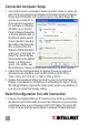
Connected Computer Setup 1. Turn off the mouse acceleration feature and the “Snap to” option on each of the computers/servers included in the network being configured. Mouse synchronization can function properly only when these two options are turned off on all connected computers.
connectivity; if unlit, the connection isn’t ready. When lit, the amber LED indicates 100 Mbps connectivity. NOTE: If your LAN is using a network segment other than 192.168.1.xxx, consider configuring one of the computers with an IP address of 192.168.1.xxx. The factory defaults of the switch are as follows: Port base: 5900 IP address: 192.168.1.200 Subnet mask: 255.255.255.0 Default gateway: 192.168.1.254 DNS: 192.168.1.1 2.
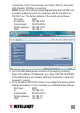
it means you’ll use 6080 for the viewer port base and 6088 for the SSL browser connection (). Thus, you would enter https://192.168.1.36:6088 in the browser address bar to obtain Web Management access, and within the viewer prompt window you would enter 192.168.1.36:6080. Note: The DNS setting is required only when you want to use the mail alert function to notify users of specific server alert events via e-mail. 4.
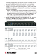
2. Go to the Download screen and download/install the Win32 viewer program. A viewer icon will appear on your desktop. NOTE: You can download either a Win32 or Java version of the viewer, but the Java viewer requires that Java Runtime Environment 1.5.0 or above be already installed on your computer client. The Java viewer itself won’t have an installation process: Just double-click on it to run the program. 3.
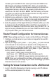
5. With the Connection Details screen displayed again (see Step 3 images), enter the access IP and viewer port number in the “Server and Card” field: • Within a LAN: : (e.g., 192.168.1.36:6080) • From across the Internet through a firewall/router: : (e.g., 61.232.134.120:6080) Click “OK.
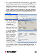
Switch Display Optimization 1. Open a viewer connection (see previous section). 2. Check for video quality and proper screen centering on the viewer screen. If a screen is not properly centered it will have a black strip (offset) on edge of the screen. To make any adjustments, go to the viewer’s Quick Menu (by clicking the title bar icon of the viewer window) and select Adjust Screen. For details about these settings, refer to the several Viewer Connection sections in the user manual.
Apply Settings screen and click “Restart Servers” to make the name modifications effective. For details, refer to KVM Server: Computers in the user manual. 3. Establish a new viewer connection and you’ll see the Select Computer box now displays the newly specified computer names.
Changing the Viewer Security Level Three viewer connection security levels are available: • Level 1 — No SSL encryption, no SSL authentication • Level 2 — 256-bit encryption, server authentication by client • Level 3 — 256-bit encryption, full authentication (requires the installation of certificates) By factory default, the security level is set at Level 2. 1. Go to the Main: Security screen on the switch’s Web Management interface. 2. Choose the desired viewer connection security level.
secure policy than either No Password or Global Password. If you select Global Password, you will need to enter a global password to be used by all users for viewer access to the switch. Other Settings Power Control, RADIUS Accounting and Remote Authentication are disabled by factory default. If you are not going to use these features, there is no need to enable them; otherwise they’d take up switch resources during booting time.
INTELLINET NETWORK SOLUTIONS™ offers a complete line of active and passive networking products. Ask your local computer dealer for more information or visit www.intellinet-network.com. Copyright © INTELLINET NETWORK SOLUTIONS All products mentioned are trademarks or registered trademarks of their respective owners.