PRO SERIES Network Camera & Video Server USER MANUAL INT-PSNC-UM-1106-06
Table of Contents Safety and Regulatory Notices .................................................................................................... 3 Section 1: Product Overview 1.1 About the Pro Series Network Cameras and Video Servers........................................... 5 1.2 Main Features and Benefits ........................................................................................... 5 Section 2: Physical Description 2.1 Package Contents ...................................................
Appendix A: Frequently Asked Questions (FAQ)....................................................................... 74 Appendix B: Accessing the Camera via HyperTerminal…………………................................. 79 Appendix C: Troubleshooting..................................................................................................... 81 Appendix D: Utilizing IP addresses on a Local Network………….............................................. 83 Appendix E: Updating Firmware...............................
Video Standard and Product Classification As the video standard varies from country to country, users are asked to check it first and choose the right model. The two most common video standards used are NTSC and PAL. NTSC is the video system or standard used in North America and most of South America. In NTSC, 30 frames are transmitted each second. Each frame is made up of 525 individual scan lines. PAL is the predominant video system or standard mostly used overseas.
1: Product Overview 1.1 About the Pro Series Network Cameras and Video Servers The Pro Series Network Cameras and Network Video Server are all-in-one networking devices that contain a digital color camera (or a connection for analog CCTV cameras), a powerful Web server, an optimized embedded operating system, hardware for image compression and a physical Ethernet connection. The products do not need any additional software or hardware.
Dual Mode Compression (only certain models) For application providers, system integrators and other APs, this camera supports three types of video: 1) MPEG4 video; 2) M-JPEG compression; and 3) MPEG4+M-JPEG mode. Full Duplex Two-Way Audio (only certain models) Full duplex two-way audio is available by connecting an external microphone and speaker to the camera. IEEE 802.
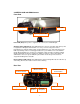
2.2 MPEG4 CCD and CMOS Camera Front View Power LED Network Activity LED Operating Status LED Power LED (Red): Once power is supplied to the camera, the red LED will light. Operating Status LED (Green): This LED indicates the camera’s operating status. Once power is supplied, the LED lights and then blinks once every second as long as the video is transmitted on the network during normal operation. When there is no video transmission, the LED stops blinking.
Power Connector: Only use the supplied AC adapter to avoid any possible damage from electric shock. Network Connector: Connect 10Base-T Ethernet or 100Base-TX Fast Ethernet cable. GPIO Connector: To connect external devices such as infrared sensors, alarms or motion detectors (refer to Appendix F: I/O Connector). Mini DIN Connector: To connect external devices such as the external zoom/focus lens mechanism, or to connect directly to a serial port for camera configuration via HyperTerminal.
2.4 Network Video Server Video Input: To input video signal through a coaxial cable Video Output: To output video signal through a coaxial cable. Video Input Video Output On Air Network LED Power LED On Air LED (Green): This LED indicates the Video Servers operating status. Once power is supplied, the LED lights and then blinks once every second as long as the video is transmitted on the network during normal operation. When there is no video transmission, the LED stops blinking.
I/O Connector: To connect external devices such as infrared sensors, alarms or motion detectors (refer to Appendix F: I/O Connector). Ethernet (Network Connector): Connect 10Base-T Ethernet or 100Base-TX Fast Ethernet cable. SPK: Use to connect to an external speaker for audio communication. The audio sent over the network from a connected Video Server client can be delivered through this externally connected speaker. MIC: The external microphone for audio input.
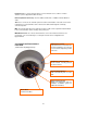
Rear View Terminal Block 6-pin input/output for external alarm devices and sensors RJ-45 Network Connector IEEE802.3af PoE-compliant network connector. Power connector 12 V DC power input for non-PoE installations. BNC Loop-through port Analog video output signal for CCTV systems and monitors. Audio IN/OUT Connector for active speakers and high-gain microphones and line in sources 2.
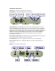
Rear View RS232 Connector Serial port connection for HyperTerminal access; See Appendix B. Network Connector Connect 10Base-T Ethernet or 100Base-TX Fast Ethernet cable. Power Connector Input connector for external 12 V DC Power supply. Terminal Block Connect external devices such as sensors and alarm devices, or power external devices through the camera; See Appendix F for details. 3: Installation Summary and Examples 1. Connect the Ethernet and power to the Pro Series Network Camera. 2.
Installation Example: Wireless Camera Installation Example: Network Video Server 13
4: Assigning an IP Address and Accessing the Camera’s Homepage 4.1 Connecting the Camera to a PC Connect with a direct cable (non-crossover UTP cable) when connecting the camera to a switch, hub or router. Connect with a crossover UTP cable when connecting the camera to a PC.
4.2 Setting up the IP Address Using IP Installer To access the camera, you need to assign an appropriate network IP address. Run the IP address installation program (IP Installer.exe) on a PC that is connected to the same local network as the camera. You can download IP Installer from http://www.networkipcamera.com. IP Installer is compatible with Windows 9x, Me, 2000, XP and Vista. 1. Run IP Installer after the camera is booted (wait until the Operating Status LED blinks every second). 2.
4.3 Accessing the Camera’s Homepage Access the camera to monitor real-time images over the Internet and configure the camera settings through any standard Web browser on a local or remote network. The following Web browsers are supported. - MS Internet Explorer 5.x, 6.x and 7.x (ActiveX + Java) - MOZILLA Firefox 1.x., 2.x (Java) - MOZILLA 1.
MS Internet Explorer – JPEG Stream Mode Both options, ActiveX and Java, are available in this operational mode. If you can run and install ActiveX controls, you should select ActiveX as your preferred viewing program, as it offers higher frame rates and better functions. MS Internet Explorer – MPEG4 Stream Mode Java is not available in MPEG4 Stream mode and the option is therefore grayed-out. Non-MS Internet Explorer – JPEG Stream Mode Java is the only choice given.
Non-MS Internet Explorer – MPEG4 Stream Mode Java is the only choice given, but the warning message tells you that even though you are able to login you won't be able to see the live image. You still can access the administration menu to make changes to the settings. Camera model 550710 does not support MPEG4 streaming and the options shown above do not apply. The other options are described below. Username and Password Enter a username and password to access the camera.
ActiveX Installation for MS Explorer Users (automatic) The first time you login to the camera using ActiveX, you are notified that a required plug-in / ActiveX control is required. You need to allow the installation of ActiveX by clicking "Yes" to the question "Do you want to install the program?" on the pop-up window. The installation will then take place. It is normal for this process to take up to 30 seconds. After the installation you will be taken to the Network Camera Homepage.
Click "Next" to continue with the installation. When you see the message above, you have successfully installed the ActiveX control. Restart MS Internet Explorer and re-connect to the camera.
4.4 Homepage Options (MPEG4 Cameras) Once the login procedure is complete, you can view the Pro Series (MPEG4) Network Camera homepage. Below is an overview of the different pages for the different models for both Java and ActiveX.
MPEG4 CMOS Cameras with Digital Pan Tilt Zoom - ActiveX version Video Size You can select a viewing image size from 0.5 to 2. This function represents a digital zoom. It does not change the physical resolution of the image. At high resolution (D1) the options "x1.5" and "x2" are not available. Audio Select audio "on" for starting audio communication; select "off" to stop audio communication over the network with the external microphone and speaker connected to the camera.
Record Video Users can save real-time images from the camera on a PC. Click "Start," then select the folder to save the images in. (The image is saved as an AVI file.) Once the camera starts to save images, the green LED indicator will start blinking. To stop saving, click "Stop" and the LED indicator will stop blinking. You can view a saved image with Windows Media Player or RealTime. For the initial playback of a saved image, click "Install XviD.
4.5 Homepage Options (JPEG CMOS Camera 550710) The camera homepage of the 550710 camera looks different than the screens of the other models; however, most functions work the same. Expansion You can select a viewing image size from 0.5 to 2. This function represents a digital zoom. It does not change the physical resolution of the image. At high resolution (VGA) the options "x1.5" and "x2" are not available. Frame rate You can control the frame rate of the video with this option.
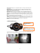
5: Adjusting the Camera Lens 5.1 Adjusting the Focus To get the finest image, adjust the lens focus according to your environment. Before adjusting, turn the set screw counterclockwise, then turn the lens in either direction till you get the most well-defined image edges while viewing the picture quality on your Web browser. When you finish adjusting the lens, turn the set screw clockwise to fix it in place. Set Screw Turn this part either clockwise or counterclockwise to adjust the lens focus.
6: Administrator Menu You can control the configurations of the camera using the administrator tools, which can be accessed only by an authorized user. If non-authorized users try gaining access, you may see a warning message "You are not an administrator." 6.1 Overview of the Administration Menu The table below provides a one-step overview of the Administrator Tools: Image Configuration To Configure compression rate, image size, brightness, contrast, etc.
6.2 Image Configuration 6.2.1 MPEG4 CCD Cameras, Dome Cameras and Network Video Server Rate Control The bit rate used in video encoding has a direct impact on the video quality and the bandwidth used to stream video over the network. As opposed to constant bit rate (CBR), VBR files vary the amount of output data per time segment. VBR allows a higher bit rate (and therefore more storage space) to be allocated to the more complex segments of media files while less space is allocated to less complex segments.
Lowest Bit Rate/Quality -> smallest network bandwidth usage Above image illustrates the effects of lowering the video quality. You have full control over the amount of bandwidth the camera can use, to the point where it becomes difficult to identify any objects in the image due to heavy compression damage. Highest Bit Rate/Quality -> highest network bandwidth usage: The effects of compression are minimal at the best image quality settings.
Resolution Select the resolution for output video. Pro Series CCD Network Cameras support three types of image resolution. NTSC: D1 (720x480), VGA (640x480) and CIF (352x240); PAL: D1 (720x576), VGA (640x576) and CIF (352x288). The Digital PTZ CMOS camera supports 720x480, 640x480, 352x240 and 320x240 pixel image resolution. Frame Rate Select the frame rate according to your preference.
De-Interlace Interlaced video is composed of two fields that are captured at different moments in time. When displayed on a typical computer screen, interlaced video frames will exhibit motion artifacts when both fields are combined and displayed at the same moment (today's computer screens are progressive scan monitors which display the image line by line from top to bottom without interlacing). These motion artifacts are visible in the form of horizontal lines.
Hue Most sources of visible light contain energy over a band of wavelengths. Hue is the wavelength within the visible-light spectrum at which the energy output from a source is greatest. Normally there is no need to change the default value (8), but if you wish to experiment with different hue values to achieve different effects, the camera offers 15 values to choose from. Examples of different Hue Values (from left to right: 0, 4, 8, 10). Actual results may vary, depending on the camera model.
6.2.2 MPEG4 CMOS Cameras The basic options are the same, except for the ones mentioned below: Auto Exposure Enable or disable the Auto Exposure. The exposure target can be used to define the brightness of the image. 128 is the default value. The higher the value, the brighter the image. Minimum Image Sensor Rate Here you can define the minimum frame rate of the image sensor.
6.2.3 JPEG CMOS Camera 550710 Compression Rate You can set the image compression rate here. A value of "10" equals the best possible compression. Value "1" offers the best image quality. It is recommended to use compression values of 8 – 10 for best results. Image Size Select the resolution for output video. The Pro Series Network Camera 550710 supports three types of image resolution: 160 x 120 pixel, 320 x 240 pixel and 640 x 480 pixel.
Sharpness This value lets you control the sharpness of the image. Lower values generate a smoother image; higher values generate a crisper image. Values of "4" and "5" give you good results in general. Exposure Mode This controls the exposure mode of the camera. The exposure mode has a very direct impact on the brightness of the image. It is recommended to leave this value set to "Auto." When you activate the manual mode, you need to specify the exposure mode value in the Exposure field.
6.3 Network Configuration 6.3.1 MPEG4 Cameras, Dome Cameras and Network Video Server This screen defines the network type and addresses of the camera. Here you can configure the camera’s IP address, the DNS server address and the SMTP server IP address.
Set IP address, Subnet Mask, Gateway Address To set the IP address, subnet mask and gateway address manually, select "manually" in the combo box. If you have any trouble configuring network system information, contact your network administrator. Knowledge about IP addresses and TCP/IP is required for the configuration task. Set DHCP When selecting "using DHCP," the IP address, subnet mask address and gateway address are being obtained from a DHCP server.
RTSP Port Number RTSP stands for Realtime Streaming Protocol and allows RTSP enabled video playback clients such as VLC Media Player or MPlayer to play back the live video from the network camera. For more information refer to section "RTSP Video Playback". We recommend using the default value " 554". 1st, 2nd DNS Server Address To map between an IP address and domain name, you should enter your DNS server address.
6.3.2 JPEG CMOS Camera 550710 The network settings for the camera model 550710 are virtually identical to those of the MPEG4 models. Since the 550710 camera does not support Audio, the audio-related port settings are not shown.
6.4 User Configuration 6.4.1. MPEG4 Cameras, Dome Cameras and Network Video Server This screen is used to define and configure user accounts for camera access. ID User Name must be between 5 and 10 characters. Password Password must be between 5 and 10 characters. Maximum Frame Rate You can define the maximum frame rate this user is allowed to receive. This function can be useful if you allow public access to your camera; e.g.
6.4.2. JPEG CMOS Camera 550710 ID User Name must be between 5 and 10 characters. Password Password must be between 5 and 10 characters. Maximum Frame Rate You can define the maximum frame rate this user is allowed to receive. This function can be useful if you allow public access to your camera; e.g., you may have the camera live image integrated into an HTML page on your Web site, but want to keep the users from consuming all of the available bandwidth.
6.5 Event Trigger Configuration 6.5.1 MPEG4 Cameras, Dome Cameras and Network Video Server This screen is used to receive captured video through e-mail or an FTP. You may also connect external devices, such as an infrared sensor or alarm sensor, to use with the provided terminal block (refer to Appendix F: The I/O Connector). Trigger Condition This is to select options for sending an event signal to the camera. The camera receives an event signal from external devices such as an infrared sensor.
Motion Detection Sensitivity: This is to configure the level of motion detection sensitivity. The level is composed of five levels, from 0 to 4. Value 0 is the least sensitive setting. At this setting, the camera may "overlook" a lot of motion. Value 4 is the most sensitive setting. At this setting, the camera will likely cause a lot of false alarms because the tiniest movement – even the video compression – which can create compression artifacts, can trigger an alert.
Image Capture Option This is to configure image capture options when an event is triggered. When an event occurs, you can get the pre-event and post-event images by setting "Before event" and "After event." Before event: You may set the starting time to capture an image before the event is triggered. (Input limitation is from 0 to 30 seconds.) After event: You may set the finishing time to capture an image after the event is triggered. (Input limitation is from 0 to 30 seconds.
Image Capture option limitation The configuration for the image capture option affects memory capacity. If the configuration uses excessive memory, the warning message “Not enough memory…" will display. The total image capture frame rate must be no more than 120 fps due to memory size. (Before event time + After event time) x (Image capture frame rate) must be under 120.
6.5.2 JPEG CMOS Camera 550710 The Event Trigger Configuration of the camera model 550710 is very similar to the MPEG4 models. There are two main differences here: a) No Motion Detection Area You cannot define the motion detection area. If you enable motion detection, the entire image area is being monitored. b) No upload of AVI video files This camera model only supports the upload of JPEG images.
6.6 System Configuration 6.6.1 MPEG4 Cameras, Dome Cameras and Network Video Server This screen is used to configure camera name, location, operation mode and system information, as well as time configuration for the camera. Camera Name Define the camera name, maximum of 10 characters. Camera Location Define the camera location, maximum of 10 characters. Operation Mode and Output Stream Type There are three operation modes for the camera: Single (MPEG4 Only), Single (JPEG Only) and Dual (MPEG4+JPEG).
Image File Name This option is used to for accessing the JPEG images with ".jpg" extensions. The file name should be less than or equal to 10 characters. Audio On/Off Activate or deactivate the camera's audio function. This option can be important in situations in which, by law, you are not allowed to do video surveillance that includes audio and you are required to install a camera without audio support.
Synchronized with NTP Server The camera automatically configures the date and time through the NTP (network time protocol) server. The NTP server is based on Greenwich time. Select the NTP server, IP address and time zone to set the date and time automatically, then click "submit." NOTE: If this procedure doesn’t work, it could be due to a network error. Select another NTP server and IP address or set the date and time manually.
6.7 Wireless Configuration (for wireless cameras only) This screen is used to configure wireless settings to match your access point for a wireless network connection. 6.7.1 Wireless Setup 1. Select the operation mode to determine the type of wireless communication for the Pro Series Wireless Network Camera: Infrastructure or Ad hoc. The default setting is Infrastructure. 2. Set the service area name (SSID) in accordance with the access point settings to which the camera should connect. 3.
Authentication: WEP uses two types of authentication methods to authenticate the connection request. One is Open key authentication, in which all clients are allowed to authenticate; the second is Shared key authentication, which allows the AP (access point) to send the client a challenge text, which the client encrypts and returns to the AP. If the AP successfully decrypts the challenge text, the client is authenticated. Set the authentication type as per the access point authentication type.
WPA & WPA2 (personal) Wi-Fi Protected Access (WPA and WPA2) is a more effective way to secure wireless (Wi-Fi) computer networks. It was created in response to several serious weaknesses which researchers had found in the previous system, Wired Equivalent Privacy (WEP). WPA implements the majority of the IEEE 802.11i standard, and was intended as an intermediate measure to take the place of WEP while 802.11i was prepared.
IMPORTANT Infrastructure Mode This is an 802.11 networking framework in which devices communicate with each other by first going through an access point (AP). In Infrastructure mode, wireless devices can communicate with each other or can communicate with a wired network. When one AP is connected to a wired network and a set of wireless stations, it is referred to as a basic service set (BSS). An extended service set (ESS) is a set of two or more BSSs that form a single sub network.
7: PoE (Power over Ethernet) Support Power over Ethernet, or PoE, technology describes a system to transmit electrical power, along with data, to remote devices over standard twisted-pair cable in an Ethernet network.
PoE Office Switch 8-Port Desktop, IEEE 802.3af compliant, Endspan 10/100 Mbps Fast Ethernet Switch for eight network cameras. Part Number / Model: 503358 PoE Web-Smart Switch 8-Port Desktop, IEEE 802.3af compliant, Endspan 10/100 Mbps Fast Ethernet Switch for eight network cameras. Switch provides smart functions such as VLAN, QoS and port controls. Part Number / Model: 502917 Fast Ethernet Rackmount PoE Switch 16-port, IEEE 802.
8: Multi-Viewer Application for Windows With "Multi-Viewer for Windows," it is possible to view up to four different network cameras on one PC monitor. Installation Insert the supplied CD into the CD-ROM drive of your computer and open the "Multi-Viewer" folder. Find "Multiviewer.exe" and double-click it to start the installation. Click Next. Click "Browse" to select the installation folder and click "Install" to begin the installation. Wait for the installation to finish.
Multi-Viewer opens and the following screen appears: Configuration Page Access the IP address, ports, frame rate, username and more. Refresh Re-connect to the selected camera. Delete Remove the selected camera from the configuration. End Program Quit Multi-Viewer.
Expand/Collapse the Camera Information and Message Window Camera Information Displays information such as frame rate (F/S), camera type, stream type, camera IP and user name. Log Messages Displays information about changed configurations and connected cameras. Adding a camera To add a camera, simply double-click the location on the screen (upper left, lower left, upper right and lower right square). Enter the correct settings in the configuration window and click "OK.
Repeat the steps for each camera. Below is a sample screenshot of Multi-Viewer showing four cameras: Multi-Viewer also supports Pro-Series JPEG Cameras such as model 550710 (wired) and 550703 (wireless). The JPEG cameras show a grey frame around the live image (see above image 2, 3 and 4), whereas the MPEG4 models do not. Multi-Viewer does not have the ability to create recordings. It is merely designed to monitor four cameras on one screen.
9: ETSP Client ETSP stands for "Event Triggered Saving Program." This utility allows you to automatically record video on the HDD of your computer whenever the camera detects a motion. The latest version of ETSP Client is available on networkipcamera.com as a free download. Getting Started To use ETSP Client, you first need to activate the ETSP option in the Event Trigger Configuration of the camera. See section 6.5 for additional information. 1. Activate Motion Detection 2.
Click "Add". Define the location where the video should be saved. Specify the length of the recorded video (in minutes). Enter the camera's IP address. ETSP port and video port need to be entered here. If you have changed the port settings in the camera, you need to make adjustments here. Click "Save" to save the settings and open the main screen of ETSP Client.
The IP address of the camera you are monitoring is displayed here. If multiple cameras are set up, you can select them from the drop-down list. Enter a valid username and password for the camera (an administrator account is required). Click this button to open / close the Status window. Click on "Login" to start the monitoring and recording process. ETSP Client is now connected to the camera.
When the camera detects motion, ETSP Client will trigger the recording. ETSP Client shows the video and displays additional information in the status message window. The image below shows an example of ETSP Client actively recording a video on the HDD. Real Time Status window Live Video window: Whenever a recording is active, this window opens and lets you monitor the activity in real time.
10: RTSP Video Playback RTSP stands for "Real Time Streaming Protocol ." RTSP enabled video streaming clients, such as MPlayer, can access the video data stream of the camera directly and you can watch the live video without connecting to the camera with your Web browser first. MPlayer is freeware. RTSP Playback in MPlayer for Windows 1a. Activate MPEG4 streaming in the system configuration of the camera. 1b.
3. Enter the correct address to your camera URL: rtsp://guest:guest@192.168.0.221/mp4media guest:guest = valid user name and password 192.168.0.221 = IP address or web address of your camera mp4media = fixed part of the URL 4. Click "OK" and the video playback will start in two – five seconds. Note: 1. RTSP support is limited to the MPEG4 camera models; camera 550710 does not support RTSP. 2. RTSP support may not work with all RTSP enabled clients; e.g.
11: SSL Encryption / Access via HTTPS The MPEG4 cameras are equipped with SSL encryption, a safe way of accessing your camera. SSL encryption ensures, that the data traffic between your camera and the computer is encrypted. Access to the camera via HTTPS: To utilize HTTPS, you need to enter the following address in your Web browser: Note: Use "https" instead of "http". You will be presented with a security message (may vary depending on your system).
Click on "View Certificate" to view the details. The image on the left shows a screenshot of MS Internet Explorer 6.x. The certificate must be issued to www.networkipcamera.com. You may be seeing the warning below: This message is shown, whenever a web site with secure and nonsecure elements is shown. Nonsecure elements can be images which are not crucial for the security. The question should be answered with "Yes".
12: Remote Access to a Camera & Router Setup To gain access to a camera in your local network over the Internet, certain ports need to be opened and forwarded in your router.
Setup Example 1: INTELLINET NETWORK SOLUTIONS MIMO Wireless Turbo G Router and Wireless N Router: Click on NAT -> Virtual Server. Check (x) Enable Virtual Server. Enter the camera IP address, along with the Web server (private and public port should be identical), select type = TCP and enter a description in the comment field. Click on ADD. Repeat the steps for the other ports. The end result should look like this: Click "Apply" to save the settings.
Setup Example 2: INTELLINET NETWORK SOLUTIONS Wireless Super G Router (Model 502566): Click on Access -> Virtual Server. Check (x) Enable Virtual Server. Enter a descriptive name and the public and private ports, then select TCP as the protocol and enter the IP address of the camera as the LAN Server. Click on "add.
Setup Example 3: INTELLINET NETWORK SOLUTIONS Wireless G Broadband Router (Model 523431), 4 Port Broadband VPN Router (Model 523608), 8 Port Broadband VPN Router (Model 523615) and Dual WAN Router (Model 524049). Click on NAT -> Port Forwarding. Enter a rule name, external port range, camera IP address and internal port range. The above example shows port 80. Click "Add" to save the rule. Repeat the steps for the other ports.
13: Developer Information This section of the user manual contains useful information for software developers and Web programmers. 13.1 Software Development Kit (SDK) Software developers can download an SDK for INTELLINET NETWORK SOLUTIONS ProSeries cameras and network video servers from www.networkipcamera.com. The SDK consists of different documents, sample programs and sample code snippets for various applications.
13.2 Direct Access to internal JPEG To utilize the camera in third-party video surveillance programs, you can activate the direct image access. It allows accessing the internal JPEG image of the camera that other programs can download. You can define the behavior of this function in the System Configuration of the camera: Direct public access to image via HTTP: enable: Any user can access the image. No username or password is required to see the image.
13.3 Motion-JPEG Access The MPEG4 cameras support a dual-mode streaming capability. This means that the camera can output MPEG4 and Motion-JPEG video data simultaneously. Motion-JPEG is the preferred method when using the camera with third-party video surveillance applications. It is widely supported, and is often the only image format accepted by courts, who consider MPEG4 compression too lossy. Motion-JPEG video, on the other hand, cannot compress video data as effectively as MPEG4 does.
Appendix A: Frequently Asked Questions (FAQ) 1. What is the default IP address of the network camera? The default IP address is 192.168.1.221 2. I use a MacOS or Linux system and cannot use IP Installer to set up my camera. How can I install the camera without that tool? 1. You will need to change the IP address of your MacOS or Linux PC so that it is in the range of the camera's default IP address: 192.168.1.221 (network mask 255.255.255.0). For example, you can set the IP address of your computer as 192.
6. How do I activate the E-mail Function? a) Camera Network Configuration DNS Server Address A DNS server is required if you enter the SMTP server using the domain name. If you enter the IP address of the SMTP server you do not need to specify DNS server information, but if you enter the domain name of your mail server (e.g., mail.myserver.com or smtp.myserver.com) you need to type in at least one DNS server. SMTP Server (max.
7. The camera does not send any e-mails. Why? 1. The problem occurs because the camera cannot contact the E-mail server Check: - Is the e-mail (SMTP) server address correct? (Network Configuration) - Did you specify the correct gateway IP address? (Network Configuration)? - Did you specify correct DNS servers? (Network Configuration) - Did you enter the correct e-mail address? (Event Trigger Configuration) - Did you specify the e-mail title? (Event Trigger Configuration) 2.
9. What does the FTP Rename option in the Event Trigger Configuration do? The FTP Rename option should be activated whenever the camera uploads the same image (same image name) to the FTP server. Typically this is an application where the camera uploads still images to your Web site every xx seconds and you display the image on your Web site. Without the Rename option enabled, the following will happen: The FTP upload process consists of different steps. 1. Login 2. Delete existing file 3.
11. Even though I enter the right ID and password to log in, the error message "You must login first" appears. What’s wrong? Open "Internet Options" in MS Internet Explorer and then click on the "Security" tab to view the setting. (If set on "High," ActiveX would have a problem downloading.) You can manually install the ActiveX control as described in section 4.3 or change the security settings to a lower level. 12.
Appendix B: Accessing the camera via HyperTerminal NOTE: This section is for advanced users only. HyperTerminal is a basic program for Windows 9x/NT/2000XP/Vista. A PC can communicate with external devices through the serial port by using this program. The steps you should take to set the HyperTerminal are as follows with a Windows 2000 OS. The camera can be programmed via HyperTerminal, but only a few options are available.
3. Configure the parameters as shown below: (all MPEG4 models) (JPG CMOS Camera 550710 uses the following values: 19200 – 8 – None – 1 – None) 4. The window should display as below when configured properly. You can see real-time messages generated by the camera operating system which can be recorded by going to "Transfer" and clicking "Capture Text." In case of a camera malfunction, you can record this log should the technical support team ask for the information.
Appendix C: Troubleshooting This appendix provides useful information to help you to resolve any difficulty you might have with your Pro Series Network Camera. Fault symptoms, possible causes and remedial actions are provided within a quick reference table. PINGing Your IP address By sending a packet to the specified address and waiting for a reply, the PING (packet Internet grouper) can determine whether a specific IP address is accessible.
(hub-to-hub) cable. If the above actions don’t resolve the problem, the camera maybe faulty. In this case, try to localize the problem by connecting the camera to the serial port of a local computer, using the RS-232 cable. Verify that you are using the provided power supply. The Power LED is not constantly lit The Network LED is off Faulty power supply The Operating Status LED is off Faulty connection 1.
NOTE: If you still have a problem with your camera after following the above recommendations, contact your dealer or check the INTELLINET ACTIVE NETWORKING Web site: http://www.networkipcamera.com. Appendix D: Utilizing IP Addresses on a Local Network Introduction Access to the Internet is achieved via Internet IP addresses. Currently, IP addresses are limited. There are five classes of networks, and each network contains IP addresses.
Subnet Mask: 255.255.255.0 Broadcast Address: xxx.xxx.xxx.255 IP addresses: xxx.xxx.xxx.2 - xxx.xxx.xxx.254 2. To use as two sub-networks (1/2 + 1/2) Sub-Network ID: xxx.xxx.xxx.0 Gateway Address: xxx.xxx.xxx.1 Subnet Mask: 255.255.255.128 Broadcast Address: xxx.xxx.xxx.127 IP addresses: xxx.xxx.xxx.2 - xxx.xxx.xxx.126 Sub-Network ID: xxx.xxx.xxx.128 Gateway Address: xxx.xxx.xxx.129 Subnet Mask: 255.255.255.128 Broadcast Address: xxx.xxx.xxx.255 IP addresses: xxx.xxx.xxx.130 - xxx.xxx.xxx.254 3.
Appendix E: Updating Firmware CAUTION: The process for updating current firmware is already installed in your camera. If you begin the process, follow the manual instructions. During the process, do not disconnect the network or power source, and avoid any physical shock to the camera. Otherwise, the camera can be seriously damaged and fail to function properly. If firmware fails to update, or if the camera does not operate properly after a firmware update, contact your local dealer.
Appendix F: The I/O Connector (MPEG4 Cameras) The I/O Connector provides the physical interface to a digital output and a single digital, photocoupled input that is used for connecting a variety of external alarm devices to the Pro Series Network Camera, including infrared sensors, switches and alarm relays. In combination with the configurable alarm facilities, you can quickly develop a variety of security applications that are triggered on time- or alarm-based events. No.
Appendix G: Dynamic Domain Name System (DDNS) Your Internet service provider (ISP) provides you with at least one IP address that you use to connect to the Internet. The address you get may be static, meaning it never changes, or dynamic, meaning it’s likely to change periodically. Just how often it changes depends on your ISP. A dynamic IP address complicates remote access since you may not know what your current WAN IP address is when you want to access your network over the Internet.
2. If you didn’t register your ID, click "Create Account" and register your ID. Or, just log in with a registered ID. NOTE: Read and follow the instructions about cookies! 3. Enter your information highlighted by the red circles and click "Create Account.
4. An "Account Created" message will display. 5. You will receive an e-mail as shown bellow. Click the confirmation URL circled in red. 6. Click on "Login" and log in with your user ID and password.
7. Go to Services, then DNS Services and Dynamic DNS, then click "Create Hosts." 8. Enter a Hostname(a), select domain name(b), then click "Add Host"(c). 9. After successful registration, the registered information will be displayed. NOTE: After the DDNS registration is completed, enter the DDNS settings for the camera.
DDNS Registration for the Pro Series Network Camera 1. After setting up ODS or DynDNS, open the Network Configuration page of the administrator menu. 2. Enter at least one DNS server. 3. In the DDNS Registration section, a. Click "enable" b. Click on the DDNS Server field c. Select the DDNS server (ODS or DynDNS) you want d. Fill in your registered user ID e. Fill in your registered password f. Fill in the host name g. Click "submit" 3.
Appendix H: Reinstating the Factory Default Settings This information details how to set the default settings for the Pro Series Network Camera. In certain circumstances, it may be necessary to restart or reinstate the factory default settings for your camera. This is done by pressing the Reset button or by using HyperTerminal settings. Pressing the Reset Button 1. Using a paper clip or any sharp pin, press the Reset button on the back of the camera. 2.
Appendix I: Glossary of Terms ActiveX - A control (or set of rules) used by a browser. ActiveX controls are often downloaded and installed automatically as required. ARP - Address Resolution Protocol. A method for finding a host's Ethernet address from its Internet address. The sender broadcasts an ARP packet containing the Internet address of another host and waits for it (or some other host) to send back its Ethernet address. Each host maintains a cache of address translations to reduce delay and loading.
JPEG - A standard image format, used widely for photographs. Also known as JPG. LAN - Local Area Network. A data communications network which is geographically limited (typically to a 1 km radius), allowing easy interconnection of terminals, microprocessors and computers within adjacent buildings. Ethernet and FDDI are examples of standard LANs. PING - A protocol that sends a message to another computer and waits for acknowledgment, often used to check if another computer on a network is reachable.
Appendix J: Product Specifications Pro Series Network Camera 550796 MPEG4, CCD, Day/Night, PAL Standards • IEEE 802.3 (10Base-T Ethernet) • IEEE 802.3u (100Base-TX Fast Ethernet) • IEEE 802.3af (Power over Ethernet) General • 32-bit ARM9 RISC CPU • 16 MByte video frame buffer • 8 MByte flash memory • 32 MByte SDRAM • Supported image resolutions: D1 (720 x 576), CIF (352 x 288) • Audio support: - Full duplex - Bandwidth: 300 Hz to 3.4 kHz - Audio input: 3.5 mm / 1.8" microphone input jack - Audio output: 3.
Pro Series Network Camera 503181 MPEG4, CCD, Day/Night, NTSC Standards • IEEE 802.3 (10Base-T Ethernet) • IEEE 802.3u (100Base-TX Fast Ethernet) • IEEE 802.3af (Power over Ethernet) General • 32-bit ARM9 RISC CPU • 16 MByte video frame buffer • 8 MByte flash memory • 32 MByte SDRAM • Supported image resolutions: D1 (720 x 480), CIF (320 x 240) • Audio support: - Full duplex - Bandwidth: 300 Hz to 3.4 KHz - Audio input: 3.5 mm / 1.8" microphone input jack - Audio output: 3.5 mm / 1.
Pro Series Wireless Network Camera 550178 MPEG4, CCD, Day/Night, PAL Standards • IEEE 802.11b (11 Mbps Wireless LAN) • IEEE 802.11g (54 Mbps Wireless LAN) • IEEE 802.3 (10Base-T Ethernet) • IEEE 802.3u (100Base-TX Fast Ethernet) • IEEE 802.3af (Power over Ethernet) General • 32-bit ARM9 RISC CPU • 16 MByte video frame buffer • 8 MByte flash memory, 32 MByte SDRAM • Supported image resolutions: D1 (720 x 576), CIF (352 x 288) • Audio support: - Full duplex - Bandwidth: 300 Hz to 3.4 KHz - Audio input: 3.
Pro Series Wireless Network Camera 550253 MPEG4, CCD, Day/Night, NTSC Standards • IEEE 802.11b (11 Mbps Wireless LAN) • IEEE 802.11g (54 Mbps Wireless LAN) • IEEE 802.3 (10Base-T Ethernet) • IEEE 802.3u (100Base-TX Fast Ethernet) • IEEE 802.3af (Power over Ethernet) General • 32-bit ARM9 RISC CPU • 16 MByte video frame buffer • 8 MByte flash memory • 32 MByte SDRAM • Supported image resolutions: D1 (720 x 480), CIF (320 x 240) • Audio support: - Full duplex - Bandwidth: 300 Hz to 3.4 kHz - Audio input: 3.
Pro Series Night Vision Network Camera 550291 MPEG4, CCD, Day/Night, IR Lens, PAL Standards • IEEE 802.3 (10Base-T Ethernet) • IEEE 802.3u (100Base-TX Fast Ethernet) • IEEE 802.3af (Power over Ethernet) General • 32-bit ARM9 RISC CPU • 16 MByte video frame buffer • Image buffer: 200 frames (CIF) • 8 MByte flash memory • 32 MByte SDRAM • Supported image resolutions: D1 (720 x 576), VGA (640 x 576), CIF (352 x 288) • Audio support: - Full duplex - Bandwidth: 300 Hz to 3.4 kHz - Audio input: 3.5 mm / 1.
Pro Series Night Vision Network Camera 550314 MPEG4, CCD, Day/Night, IR Lens, NTSC Standards • IEEE 802.3 (10Base-T Ethernet) • IEEE 802.3u (100Base-TX Fast Ethernet) • IEEE 802.3af (Power over Ethernet) General • 32-bit ARM9 RISC CPU • 16 MByte video frame buffer • Image buffer: 200 frames (CIF) • 8 MByte flash memory • 32 MByte SDRAM • Supported image resolutions: D1 (720 x 480), VGA (640 x 480), CIF (352 x 240) • Audio support: - Full duplex - Bandwidth: 300 Hz to 3.4 kHz - Audio input: 3.5 mm / 1.
Pro Series Wireless Night Vision Network Camera 550307 MPEG4, CCD, Day/Night, IR Lens, PAL Standards • IEEE 802.3 (10Base-T Ethernet) • IEEE 802.3u (100Base-TX Fast Ethernet) • IEEE 802.3af (Power over Ethernet) • IEEE 802.11b (11 Mbps Wireless LAN) • IEEE 802.
Pro Series Wireless Night Vision Network Camera 550321 MPEG4, CCD, Day/Night, IR Lens, NTSC Standards • IEEE 802.3 (10Base-T Ethernet) • IEEE 802.3u (100Base-TX Fast Ethernet) • IEEE 802.3af (Power over Ethernet) • IEEE 802.11b (11 Mbps Wireless LAN) • IEEE 802.
Pro Series Digital PTZ Network Camera 550468 MPEG4 + M-JPEG Dual Mode, 2.0 Megapixel CMOS, PAL/NTSC Standards • IEEE 802.3 (10Base-T Ethernet) • IEEE 802.3u (100Base-TX Fast Ethernet) • IEEE 802.3af (Power over Ethernet) General • 32-bit ARM9 RISC CPU • 16 MByte video frame buffer • Image buffer: 200 frames (CIF) • 8 MByte flash memory • 32 MByte SDRAM • Supported image resolutions: D1 (720 x 480), VGA (640 x 480), CIF (352 x 240) • Video frame rate: max.
Pro Series Digital PTZ Wireless Network Camera 550482 MPEG4 + M-JPEG Dual Mode, 2.0 Megapixel CMOS, PAL/NTSC Standards • IEEE 802.3 (10Base-T Ethernet) • IEEE 802.3u (100Base-TX Fast Ethernet) • IEEE 802.3af (Power over Ethernet) • IEEE 802.11b (11 Mbps Wireless LAN) • IEEE 802.
Pro Series Network Video Server 550376 MPEG4 + M-JPEG Dual Mode, Two-way Audio, PAL/NTSC Standards • IEEE 802.3 (10Base-T Ethernet) • IEEE 802.3u (100Base-TX Fast Ethernet) • IEEE 802.3af (Power over Ethernet) General • 32-bit ARM9 RISC CPU • 16 MByte video frame buffer • Image Buffer: 200 frames (CIF) • 8 MByte flash memory • 32 MByte SDRAM • Supported image resolutions: - PAL: D1 (720 x 576), VGA (640 x 576), CIF (352 x 288) - NTSC: D1 (720 x 480), VGA (640 x 480), CIF (352 x 240) • Video frame rate: max.
Pro Series Network Camera 550710 JPEG, CMOS, PAL/NTSC Standards • IEEE 802.3 (10Base-T Ethernet) • IEEE 802.
- notes - 107
INTELLINET NETWORK SOLUTIONS™ offers a complete line of active and passive networking products. Ask your local computer dealer for more information or visit www.intellinet-network.com Copyright © INTELLINET NETWORK SOLUTIONS All products mentioned are trademarks or registered trademarks of their respective owners.