Wireless G Broadband Travel Router user manual Model 523875 INT-523875-UM-0807-03
Thank you for purchasing the INTELLINET NETWORK SOLUTIONS™ Wireless G Broadband Travel Router, Model 523875. This router is equipped with two 10/100 M auto-sensing Ethernet ports for connecting to a LAN and cascading to another similar router. It also features 64/128-bit WEP encryption, WPA and IEEE802.1x to provide a high level of security to protects users’ data and privacy.
FCC Certifications This equipment has been tested and found to comply with the limits for a Class B digital device, pursuant to Part 15 of the FCC rules. These limits are designed to provide reasonable protection against harmful interference in a residential installation. This equipment generates, uses and can radiate radio frequency energy and, if not installed and used in accordance with the instructions, may cause harmful interference to radio communications.
table of contents section page Initial Setup..........................................................................................6 Hardware Connections.................................................................6 LED Indicators..............................................................................6 Operation Modes..........................................................................6 Login ..................................................................................
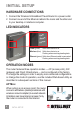
initial setup Hardware Connections 1. Connect the Wireless G Broadband Travel Router to a power outlet. 2. Connect one end of the Ethernet cable to the router and the other end to your desktop or notebook computer. led indicators Po w e r s Wirele s et Ethern Power (green) Solid when device is on. Wireless (blue) Solid when device is on. Flashing when receiving/sending data. Ethernet (green) Solid when Ethernet cable is connected. Flashing when receiving/sending data.
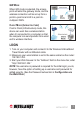
GW Mode When GW mode is selected, the access point will enter the gateway mode, and the wireless connection will be set up from a point-to-point local LAN to a point-tomultipoint WAN. Client Mode (Infrastructure) If set to Client (Infrastructure) mode, this device can work like a wireless station when it’s connected to a computer so that the computer can send packets from wired end to wireless interface. LOGIN 1.
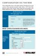
configuration via the web The Configuration menu on the upper panel is divided into four main sections: Mode (operation/wireless mode), Status, TCP/IP and Other. Select a section, then click the “Setup” button that corresponds to the desired subsection (e.g., Mode ‡ Access Point, as shown below).
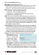
Access Point/AP Mode Settings Alias Name: Displays the device name. Disable Wireless LAN Interface: By selecting this option, you won’t be able to make a wireless connection with this access point in your network; i.e., this device will not be visible by any wireless station. Band: The drop-down menu offers three options: • 2.4 GHz (B) — 802.11b supported rate only. • 2.4 GHz (G) — 802.11g supported rate only. • 2.4 GHz (B+G) — Both 802.11b and 802.11g supported rate. The default is 2.
digits or five ASCII characters are needed if 64-bit WEP is used; 26 hexadecimal digits or 13 ASCII characters if 128-bit WEP is used. - Pre-Shared Key Format: Select “Passphrase” or “Hex” (64 characters). - Pre-Shared Key: Pre-Shared Key serves as a password. Key in an 8- to 63-character string to set the password or leave it blank, in which case the 802.1x Authentication will be activated. Make sure the same password is used on the client end.
Advanced Settings: Click “Setup” to display the Wireless Advanced Settings screen and options. • Fragment Threshold: This is a mechanism for improving efficiency when high traffic flows along in the wireless network. If your 802.11g wireless LAN adapter frequently transmits large files in the wireless network, you can enter a new fragment threshold value to split the packet. The value can be set from 256 to 2346; the default value is 2346.
redundant network overhead that could negatively affect the throughput performance instead of providing a remedy. This value should remain at its default setting of 2346. Should you encounter inconsistent data flow, only minor modifications of this value are recommended. • Beacon Interval: This is the time between beacon transmissions.
- Allow Listed: Only the stations shown in the table can associate with the AP. - Deny Listed: Stations shown in the table won’t be able to associate with the AP. • MAC Address: Enter the MAC address of a station that’s allowed to access this access point. • Comment: Enter up to 20 characters in reference to the previous MAC Address field. • Apply Changes: Click to save the new settings on the screen.
Gateway/GW Mode Settings Alias Name: Displays the device name. Disable Wireless LAN Interface: By selecting this option, you won’t be able to make a wireless connection with this portable router in your network; i.e., this device will not be visible by any wireless station. Band: The drop-down menu offers three options: • 2.4 GHz (B) — 802.11b supported rate only. • 2.4 GHz (G) — 802.11g supported rate only. • 2.4 GHz (B+G) — Both 802.11b and 802.11g supported rate. The default is 2.
must not exceed 32 characters. A device will not be permitted to join the basic service set (BSS) unless it can provide the unique SSID. An SSID is also referred to as a network name because, essentially, it is a name that identifies a wireless network. Channel Number: Allows you to set the channel manually or automatically. To set manually, just select the channel you want to specify.
without noticeable signal latency. Pre-authentication provides a way to establish a PMK (pairwise master key) security association before a client connects, with the advantage being that the client reduces the time that it’s disconnected to the network. - Authentication RADIUS Server: RADIUS is an authentication authorization and accounting client-server protocol.
“Hidden Node” problem, a situation in which two stations are within range of the same access point but not within range of each other (and are thus “hidden” from each other). When a station starts to send data to the access point, it might not notice that the other station is already using the wireless medium.
be known in advance to make a connection. • Apply Changes: Click to save and apply the current settings. • Reset: Click to clear and reset the current settings. Access Control: Click “Setup” to display the Wireless Access Control screen and options. • Wireless Access Control Mode: Select on option from the pull-down menu. - Disable: Select to disable this mode. - Allow Listed: Only the stations shown in the table can associate with the AP.
• DNS 1–3: Enter the DNS server IP address(es) provided by your ISP, or specify your own preferred DNS server IP address(es). NOTE: The DNS 2 and DNS 3 servers are optional. They will be used if/when the DNS 1 server fails. • Respond to WAN Ping: Select in order for the router to respond to ping commands originating from the WAN (Internet). NOTE: As a security precaution, this option should not be selected.
a single port number, enter it in both the Start and Finish fields. • Description: You may key in a description for the local IP address. • Save: Click to save and apply the current settings. • Reset: Click to clear and reset the current settings. • Current Virtual Servers Table: Shows the current virtual servers information. DMZ: Click “Setup” to display the DMZ screen and options.
• Enable URL Filtering: Select to enable the URL filtering function. • URL Address: You can block (“filter”) Web sites with specific URL addresses by entering the URLs in this field. • Apply Changes: Click to save the current settings. • Reset: Click to clear the current settings. • Current Filter Table: Shows the current URL address filter status. • Delete Selected: Select unwanted URL addresses and then click to eliminate them.
Client/Client Mode Settings Alias Name: Displays the device name. Band: The drop-down menu offers three options: • 2.4 GHz (B) — 802.11b supported rate only. • 2.4 GHz (G) — 802.11g supported rate only. • 2.4 GHz (B+G) — Both 802.11b and 802.11g supported rate. The default is 2.4 GHz (B+G) mode. SSID: The service set identifier (SSID) differentiates one WLAN from another; therefore, all access points and devices attempting to connect to a specific WLAN must use the same SSID.
- Use 802.1x Authentication: Select 64-bit or 128-bit encryption. Select “HEX” if using hexadecimal numbers (0-9, or A-F). Select “ASCII” if using ASCII characters. Ten hexadecimal digits or five ASCII characters are needed if 64-bit WEP is used; 26 hexadecimal digits or 13 ASCII characters if 128-bit WEP is used. - Pre-Shared Key Format: Select “Passphrase” or “Hex” (64 characters). - Pre-Shared Key: Pre-Shared Key serves as a password.
• Enable Accounting: Check to enable this function. - Accounting RADIUS Server: Enter the port, IP address and password as above. • Default Key: Make a selection from the drop-down menu. • WEP Key 1–4: As noted on-screen, these entries are limited to 5 or 10-character identifiers. • Apply Changes: Click to save and apply the current settings. • Reset: Click to clear and reset the current settings. • Close: Click to exit this configuration window.
a clear to send (CTS) message to all stations within its range to notify all other stations to defer transmission. It will also confirm to the requesting station that the access point has reserved it for the timeframe of the requested transmission. NOTE: If the “Hidden Node” problem is an issue, specify the packet size: The RTS mechanism will be activated if the data size exceeds the value you set. The default value here is 2347.
• Refresh: Click to update the display. Apply Changes: Click to save the current Client Mode settings. Reset: Click to reset the Client Mode settings. status This section offers a choice of two screens — System and Active Clients — to view the current status of settings established in the previous Mode section.
System Refresh: Click to update System Data and view any configuration changes. Active Clients Refresh: Click to update the Active Wireless Client Table and view any configuration changes. tcp/ip This section presents a screen in which you can change the settings to reconfigure the LAN Interface Setup.
LAN Interface Setup IP Address: This is the device’s local address. (Default: 192.168.1.254.) Subnet Mask: Default: 255.255.255.0. Default Gateway: Shows the default gateway IP address. DHCP: Select “Server” from the drop-down menu to enable the router to distribute IP addresses (DHCP server) and activate the Server IP field to accept a starting IP address; select “Disable” to disallow such distribution. Server IP: This is the starting IP address when “Server” is selected in the “DHCP” drop-down menu.
Upgrade Firmware Browse: Click to find and open the firmware file (the browser will display the correct file path). Upload: Click to upgrade the selected firmware. Reset: Click to restore default values. Reboot System Reboot: Click to reboot the hardware. Password Setup New Password: The maximum input is 36 alphanumeric characters. NOTE: Passwords are case-sensitive. Confirmed Password: Enter the new password again to confirm. Apply Changes: After filling in the two fields above, click to save.
computer configuration TCP/IP network, Internet and/or wireless settings may need to be checked for each connected PC to ensure they’re correct and compatible. tcp/ip network settings For PCs with the following Windows platforms, this is the first step in ensuring smooth operation in conjunction with the router. Because the router uses the TCP/IP network protocol for all functions, it is critical that the TCP/IP protocol be installed and configured on each PC.
3. On the IP Address tab, to use DHCP select “Obtain an IP address automatically.” This is the default Windows setting, which is recommended so the router will act as a DHCP server. Restart the PC to ensure it obtains an IP address from the router. If the PC is already configured, select “Specify an IP Address” and check with your network administrator before making the following changes. 4. On the Gateway tab, enter the router’s IP address in the “New gateway” field and click “Add.
5. On the DNS Config tab (“Enable DNS” selected), ensure the ISP-provided DNS address is in the “DNS Server Search Order” field; click “Add.” TCP/IP Settings for Windows NT 1. Go to the Control Panel and click to display the Network screen. 2. On the Protocols tab, select the TCP/IP protocol and click “Properties.
3. On the IP Address tab, select the network card for your LAN from the “Adapter” drop-down menu. 4. To use DHCP, select “Obtain an IP address FROM A DHCP Server.” This is the default Windows setting, which is recommended so the router will act as a DHCP server. Restart the PC to ensure it obtains an IP address from the router. If the PC is already configured, select “Specify an IP Address” and check with your network administrator before making the following changes.
5. Still on the IP Address tab, click “Advanced” to display the Advanced IP Addressing screen. 6. In the Gateways panel, click “Add” to display the Gateway Address field and enter the router’s IP address. NOTE: Click “Up·” to list the router first in the field. Click “Add” to clear/close the Gateway Address screen; click “OK” to close Advanced IP Addressing.
7. On the DNS tab, click “Add” in the DNS Service Search Order panel to display the DNS Server field and enter the DNS provided by your ISP. Click “Add” to clear/close the DNS Server screen; click “OK” to close Properties.
TCP/IP Settings for Windows 2000 1. Go to the Control Panel ‡ Network ‡ Dial-Up Connection, then right-click the Local Area Connection icon and select Properties. 2. On the General tab, select the TCP/IP protocol and click “Properties.” 3. To use DHCP, select “Obtain an IP address automatically.” This is the default Windows setting, which is recommended so the router will act as a DHCP server.
from the router. To use a fixed IP address, if the PC is already configured, select “Use the following IP address.” Check with your network administrator before making the following changes. 4. Enter the router’s IP address in the “Default gateway” field and click “OK.” (Ask your LAN administrator for the assigned IP address.) If the DNS server fields are empty, select “Use the following DNS server addresses” and enter the DNS address(es) provided by your ISP; then click “OK.
TCP/IP Settings for Windows XP 1. Go to the Control Panel ‡ Network, then right-click the Local Area Connection icon and select Properties. 2. On the General tab, select the TCP/IP protocol and click “Properties.” 3. To use DHCP, select “Obtain an IP address automatically.” This is the default Windows setting. Using this is recommended so the router will act as a DHCP server. Restart the PC to ensure it obtains an IP address from the router.
To use a fixed IP address, if the PC is already configured, select “Use the following IP address.” Check with your network administrator before making the following changes. 4. Enter the router’s IP address in the “Default gateway” field and click “OK.” (Ask your LAN administrator for the assigned IP address.) If the DNS server fields are empty, select “Use the following DNS server addresses” and enter the DNS address(es) provided by your ISP; then click “OK.
INTERNET ACCESS To configure a computer in order to use the Wireless G Broadband Travel Router for Internet access, first ensure that the DSL modem, cable modem or other relevant permanent connection is functional. Then follow the appropriate procedure below to configure the browser to access the Internet via the LAN, rather than by a dial-up connection. Windows 9x /ME/2000 1. Go to Start Menu ‡ Settings ‡ Control Panel ‡ Internet Options. 2. On the Connection tab, click “Setup.” 3.
1. Start the AOL for Windows communication software. NOTE: Only Version 2.5, 3.0 or later will work. 2. Click “Setup.” 3. Select “Create Location” and change the location name from “New Locality” to “Wireless Router.” 4. Click “Edit Location”; select “TCP/IP” in the Network field. (Leave the “Phone Number” field blank.) 5. Click “Save,” then “OK.” Configuration is complete. NOTE: Before clicking “Sign On,” ensure you’re using the “Wireless Router” location. Macintosh 1.
Other Unix Systems 1. Enter the router’s IP address in the “Gateway” field for the network card and ensure the DNS settings are correct. WIRELESS LANs & STATION CONFIGURATION All wireless stations selected to use the Wireless G Broadband Travel Router’s access point, regardless of the operating system used by the client, must have compatible settings as shown below. Mode: The mode must be set to “Infrastructure.” NOTE: The access point is always in Infrastructure mode.
In Infrastructure mode, wireless stations normally scan all channels looking for an access point. If more than one access point can be used, the one with the strongest signal is used. (This can only happen within an ESS.) Common Connection Types Cable Modems Type Details ISP Data Required Dynamic Your IP address is automatically IP address allocated when you connect to your ISP. Static (fixed) Your ISP allocates a permanent IP IP address address to you. Usually, none.
troubleshooting Problem: Can’t connect to the Wireless G Broadband Travel Router to configure it. Solution: Check that Wireless G Broadband Travel Router is properly installed/turned on, and that any LAN connections are okay. Ensure that your PC and the router are on the same network segment. (If you don’t have a router, this must be the case.) If your PC is set to “Obtain an IP Address automatically” (DHCP client), restart it.
NOTE: This should work with most applications, but it is a security risk since the firewall is disabled, and only one PC can use this feature. Problem: The PC can’t locate the Wireless G Broadband Travel Router. Solution: Your PC is set to Infrastructure Mode. (Access points are always in Infrastructure mode.) The SSID on your PC and the router are the same. Remember that the SSID is case-sensitive; for example “Workgroup” does not match “workgroup.
specifications Standards • IEEE 802.11b (11 Mbps Wireless LAN) • IEEE 802.11g (54 Mbps Wireless LAN) • IEEE 802.3 (10Base-T Ethernet) • IEEE 802.3u (100Base-TX Fast Ethernet) • IEEE 802.
www.intellinet-network.com Are you completely satisfied with this product? Please contact your INTELLINET NETWORK SOLUTIONS™ dealer with comments or questions. Copyright © INTELLINET NETWORK SOLUTIONS All products mentioned are trademarks or registered trademarks of their respective owners.