WIRELESS SUPER G ROUTER USER MANUAL MODEL 502566 INT-502566-UM-0606-02
REGULATORY NOTES AND STATEMENTS Wireless LAN, Health and Authorization for Use Radio frequency electromagnetic energy is emitted from wireless LAN devices. The energy levels of these emissions, however, are far much less than the electromagnetic energy emissions from wireless devices like mobile phones. Wireless LAN devices are safe for use per frequency safety standards and recommendations.
However, there is no guarantee that interference will not occur in a particular installation. If this equipment does cause harmful interference to radio or television reception, which can be determined by turning the equipment off and on, the user is encouraged to try and correct the interference by one or more of the following measures: 1. Reorient or relocate the receiving antenna. 2. Increase the distance between the equipment and the receiver. 3.
CONTENTS section page 1. Introduction .......................................................................6 Applications............................................................................................6 Features................................................................ ..............................7 2. Unpacking and Setup .......................................................8 Unpacking..............................................................................................
section page Wireless ........................................................................22 Status ............................................................................25 Routing ..........................................................................28 Access ..........................................................................29 Management..................................................................35 Tools .........................................................................
1. INTRODUCTION With the explosive growth of the Internet, accessing information and services at any time — day or night — has become a standard requirement for most people. The era of the stand-alone PC is waning. Networking technology is moving out of the exclusive domain of corporations and into homes with at least two computers. This integrated access device combines Internet gateway functions with a wireless LAN and Fast Ethernet switch.
FEATURES • High-speed data-transfer rate • Supports NAT for sharing one IP address with all LAN/WLAN users • Supports PPPoE and PPTP protocols for dial-up ADSL • Supports 64/128-bit WEP encryption • Supports WPA-PSK, WPA2-PSK, WPA, WPA2 security • Supports DHCP server/client • Supports UPnP (Universal Plug and Play) • Supports virtual server mapping • Supports packet filtering • Supports protocol filtering • Supports domain filtering • Supports DNS • Simple firewall protection • Upgradeable firmware for future f
2. UNPACKING AND SETUP This section provides unpacking and setup information for the Wireless Super G Router. UNPACKING Open the box of the Wireless Super G Router and carefully unpack it. The box should contain the following items: • One Wireless Super G Router, Model 502566 • One di-pole antenna • One external power adapter • One CD-ROM with this user manual If any item is found missing or damaged, please contact your local reseller for replacement.
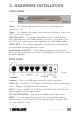
3. HARDWARE INSTALLATION FRONT PANEL Front Panel Power — This indicator lights green when the hub is receiving power; otherwise it is off. Status — This indicator blinks green when the router is working. If it stays on or off, the router is not working. WAN (Link/ACT) — This indicator lights green when the WAN port has been connected to an xDSL/cable modem successfully. It blinks green while the WAN port is transmitting or receiving data on the xDSL/cable modem.
HARDWARE CONNECTIONS Connecting the router 1. Plug in one end of the network cable to the WAN port of the router. 2. Plug in the other end of the network cable to the Ethernet port of the xDSL or cable modem. 3. Use another network cable to connect to the Ethernet card on the computer system; the other end of the cable connects to the LAN port of the router. Since the Wireless Super G Router has four ports, you can connect up to four computers directly to the unit.
4. PC NETWORK TCP/IP SETTINGS The network TCP/IP settings differ based on the computer’s operating system (Win95/98/Me/NT/2000/XP) and are as follows. WINDOWS 95/98/ME 1. Click on the “Network neighborhood” icon found on the desktop. 2. Click the right mouse button and a context menu will be shown. 3. Select “Properties” to enter the TCP/IP settings screen. 4. Select “Obtain an IP address automatically” on the “IP Address” field. 5. Select “Disable DNS” in the “DNS Configuration” field.
6. Select “None” for the “Gateway” field. WINDOWS 2000/NT Double click on the “My computer” icon on the desktop. When the “My computer” window opens, open the “Control panel” and then the “Network dialup connection”applet. Double click on the “Local area network connection” icon. Select “Properties” to enter the TCP/IP setting window. 1. In the “Local area network status” window, click on “Properties.” 2.
WINDOWS XP Point the cursor and right click on the “My Network Place” icon. Select “Properties” to enter the TCP/IP setting window. 1. Set “IP address” to “Obtain an IP address automatically.” 2. Set “DNS” to “Obtain DNS server address address automatically.
5. CONFIGURATION First make sure that the network connections are functioning normally. This Wireless Super G Router can be configured using Internet Explorer 5.0 or newer Web browser versions. LOGIN TO THE ROUTER THROUGH A WIRELESS LAN Before configuring the router through a WLAN, make sure that the SSID, Channel and WEP are set properly.
SETUP WIZARD Setup Wizard is provided as the part of the Web configuration utility. You can get the wireless router configuration ready to run in six easy steps by clicking on the “Wizard” button on the function menu. The screen at the right will appear. Click “Next” to continue. Step 1. Set your new password You can set — and/or change — the password, then click “Next” to continue. Step 2. Choose your time zone Select the time zone from the drop-down list. Click “Next” to continue. Step 3.
Step 4. Set the Internet connection Select how the router will set up the Internet connection: • Obtained IP automatically • Fixed IP address • PPPoE to obtain IP automatically • PPPoE with a fixed IP address • PPTP Obtain IP automatically (DHCP client) If you have enabled the DHCP server, choose “Obtain IP automatically (DHCP client)” to have the Wireless Super G Router assign IP addresses automatically.
PPPoE to obtain IP automatically If connected to the Internet using a PPPoE (dial-up xDSL) modem, the ISP will provide a password and username, and then the ISP uses PPPoE. Choose this option and enter the required information. PPPoE with a fixed IP address If connected to the Internet using a PPPoE (dial-up xDSL) modem, the ISP will provide a password, a username and a fixed IP address. Choose this option and enter the required information.
PPTP If connected to the Internet using a PPTP (xDSL) modem, enter your IP address, subnet mask, gateway, server IP, PPTP account and PPTP password in the appropriate fields. If your ISP has provided you with a connection ID, enter it in the “Connection ID” field; otherwise, leave it as zero.
L2TP If connected to the Internet using an L2TP (dial-up xDSL) modem, the ISP will provide a server IP account and password. Choose this option and enter the required information. Step 5. Set Wireless LAN connection Click “Enable” to enable the wireless LAN, then type the ESSID in the text box and select a communications channel. The ESSID and channel must be the same as wireless devices attempting to communicate to the router. Step 6. Setup completed Setup Wizard is now completed.
ADVANCED CONFIGURATION LAN settings This screen enables you to configure the LAN & DHCP server; set WAN parameters; create administrator and user passwords; and set the local time, time zone and dynamic DNS. LAN & DHCP server This screen allows you to set LAN and DHCP properties, such as the hostname, IP address, subnet mask and domain name. LAN and DHCP profiles are listed in the DHCP table at the bottom of the screen. Hostname: Type the hostname in the text box. The hostname is required by some ISPs.
WAN IP: Select whether you want to specify an IP address manually or allow DHCP to obtain an IP address automatically. When “Specify IP” is selected, type the IP address, subnet mask and default gateway in the text boxes. Your ISP will provide this information. DNS 1/2/3: Type up to three DNS numbers in the text boxes. Your ISP will provide this information. MAC Address: If required by your ISP, type the MAC address of the router WAN interface in this field.
Default NTP server: The Simple Network Time Protocol (SNTP) server allows the Wireless Super G Router to synchronize the system clock to the global Internet through the SNTP server. Specify the NTP domain name or IP address in the text box. Time Zone: Select the time zone from the drop-down list. Daylight Saving: Enables the user to enable or disable Daylight Saving Time. When enabled, select the start and end date for Daylight Saving Time.
Super G mode: From the drop-down list, if you choose to use Super G to enhance the speed, there are three options on Super G mode: Super G without Turbo; Super G with Dynamic Turbo and Super G with Static Turbo. The Turbo mode indicates the combination of two channels to enhance the throughput. Super G without Turbo indicates that it is on Super G mode without the channel combination. Dynamic Turbo is able to automatically detect if any Super G–based product is available.
Lifetime: Select the Lifetime of the Encryption Key (5 Minutes to 1 Day). As soon as the lifetime of the Encryption Key is over, the Encryption Key will be renewed by the RADIUS Server. Encryption Key: Select the Encryption Key Length (64 bits or 128 bits) that you would like to use. WPA/WPA2 Security RADIUS Server: 1. Enter the IP address, Port used and Shared Secret by the primary RADIUS Server. 2. Enter the IP address, Port used and Shared Secret by the secondary RADIUS Server.
Advanced This screen enables the user to configure advanced wireless functions. Beacon Interval: Type the beacon interval in the text box. You can specify a value from 1 to 1000. The default beacon interval is 100. RTS Threshold: Type the RTS (Request-To-Send) threshold in the text box. This value stabilizes data flow. If data flow is irregular, choose values between 256 and 2432 until data flow is normalized. Fragmentation Threshold: Type the fragmentation threshold in the text box.
address, IP address, subnet mask and DHCP server status. Click “DHCP Table” to view a list of client stations currently connected to the router LAN interface. Wireless: This section displays the wireless configuration information, including the MAC address, Connection status, ESSID, Channel and Authentication type. WAN: This section displays the WAN interface configuration, including the MAC address, Connection status, DHCP client status, IP address, Subnet mask, Default gateway and DNS.
Message: Displays summary information about the log entry. Source: Displays the source of the communication. Destination: Displays the destination of the communication. Note: Displays the IP address of the communication. Log Setting This screen enables the user to set router logging parameters. SMTP Server: Type the SMTP server address for the email that the log will be sent to in the next field. Send to: Type an email address for the log to be sent to.
Wireless This screen enables the user to view information about wireless devices that are connected to the Wireless Super G Router. Connected Time: Displays how long the wireless device has been connected to the LAN via the router. MAC Address: Displays the device’s wireless LAN interface MAC address. Routing This selection enables the user to set how the router forwards data: Static or Dynamic.
Delete: Select one of the entries in the static IP address table at the bottom of the page and click “Delete” to remove the entry. New: Click “New” to clear the text boxes and add required information to create a new entry. Dynamic This screen enables the user to set NAT parameters. NAT: Click the radio buttons to enable or disable the NAT function. Transmit: Click the radio buttons to set the desired transmit parameters: Disabled, RIP 1 or RIP 2.
Filters Using filters denies or allows user access. There are five types of filters to select from: MAC Filters, URL Blocking, IP Filters, Protocol Filters and Domain Blocking. MAC Filters MAC Filter: Enables you to allow or deny Internet access to users within the LAN based on the MAC address of their network interface. Click the radio button next to Disabled to disable the MAC filter. Disable: The function of the MAC filter is disabled. Allow: Only allows computers with a MAC address listed in the MAC Table.
URL Blocking You can enable URL Blocking to deny users from accessing the specified URL. Add those specified URLs in the text box. IP Filters This screen enables you to define a minimum and maximum IP address range filter; all IP addresses falling in the range are not allowed Internet access. The IP filter profiles are listed in the table at the bottom of the page. Note: Click anywhere in the item. Once the line is selected, the fields automatically load the item’s parameters, which you can edit.
Domain Blocking You can specify the domains that allow users to access or deny by clicking one of the two items. Also, add the specified domains in the text box. Protocol Filters This screen enables you to allow and deny access based upon a communications protocol list you create. The protocol filter profiles are listed in the table at the bottom of the page. Note: When selecting items in the table at the bottom, click anywhere in the item.
Enable: Click to enable or disable the virtual server. Name: Type a descriptive name for the virtual server. Protocol: Select a protocol (TCP or UDP) to use with the virtual server. Private Port: Type the port number of the computer on the LAN that is being used to act as a virtual server. Public Port: Type the port number on the WAN that will be used to provide access to the virtual server. LAN Server: Type the LAN IP address that will be assigned to the virtual server.
• Port Range: Type the port range to be used to access the application in the text boxes. Incoming: Defines which incoming communications users are permitted to connect with. • Protocol: Select the protocol (TCP, UDP or ICMP) that can be used by the incoming communication. • Port: Type the port number that can be used for the incoming communication. Add: Click to add the special application profile to the table at the bottom of the screen.
Enable: Click to enable or disable the firewall rule profile. Name: Type a descriptive name for the firewall rule profile. Action: Select whether to allow or deny packets that conform to the rule. Source: Defines the source of the incoming packet that the rule is applied to. • Interface: Select which interface (WAN or LAN) the rule is applied to. • IP Range Start: Type the start IP address that the rule is applied to. • IP Range End: Type the end IP address that the rule is applied to.
Enabled/Disabled: Click to enable or disable the SNMP. System Name: A name given to the router. System Location: A description of the location of the router (normally, the DNS name). System Contact: A description of the contact information for the person responsible for the router. Community: The SNMP system name for exchanging SNMP community messages. The name can be used to limit SNMP messages passing through the network. The default name is “public.
playing games or using these voice applications, it is recommended that Gaming Mode be disabled. PPTP: Enables the user to set up PPTP access for remote management. IPSec: Enables the user to set up IPSec access for remote management. IDENT: The default is Stealth. This enables the user to set port 113 to Stealth.
Select the file and click “Upgrade” to update the firmware to the latest release. Ping Test The ping test enables the user to determine whether an IP address or host is present on the Internet. Type the hostname or IP address in the text box and click “Ping.
6. TECHNICAL SPECIFICATIONS GENERAL Standards IEEE 802.3u 100BASE-TX Fast Ethernet IEEE 802.11g; IEEE 802.11b Protocol CSMA/CD Radio Technology IEEE 802.11g Orthogonal Frequency Division Modulation Data Transfer Rate 802.11b: 1, 2, 5.5, 11Mbps (auto sense) 802.
www.intellinet-network.com Are you completely satisfied with this product? Please contact your INTELLINET NETWORK SOLUTIONS™ dealer with comments or questions. Copyright © INTELLINET NETWORK SOLUTIONS All products mentioned are trademarks or registered trademarks of their respective owners.