RACKMOUNT CONSOLE KVM SWITCH USER MANUAL MODELS 521796, 521871, 523561 & 523578 INT-521796/521871/523561/523578-UM-0307-01
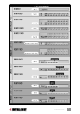
CONTENTS section page 1. Introduction .......................................................................3 Overview............................................................................. ..................4 Configurations................................................................ ......................6 2. Installation ........................................................................7 Device Connection............................................................................. ......
1. INTRODUCTION Thank you for purchasing the INTELLINET NETWORK SOLUTIONS™ Rackmount Console KVM Switch, Model 521796 (15” LCD, 8-port); Model 521871 (15” LCD, 16-port); Model 523561 (17” LCD, 8-port); or Model 523578 (19” LCD, 8-port). With a keyboard mouse, LCD panel and KVM switch module housed in an industrystandard 19” 1U- or 2U-height rack drawer, the console saves you as much as a third of the space needed for a rack cabinet.
• Password security protects computers from unauthorized use • Hotkey functions allow easy computer access • Keyboard states automatically saved and restored when switching computers • Operating system independent, transparent to all applications • Plug and Play system configuration • Keyboard and mouse can be hot plugged at any time • DDC2B compatible • Includes 6 ft. (1.8 m) PS/2 connection cable (plus 6 ft. [1.
INTRODUCTION 5
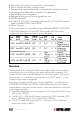
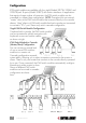
Configurations KVM switch modules are available with four, eight (Models 521796, 523561 and 523578) and 16 ports (Model 521871) with various interfaces. In applications that require a larger number of computers, the KVM switch modules can be cascaded in a master/slave configuration. NOTE: Throughout this user manual, “master” refers to the KVM switch module that connects directly to the console drawer; “slave” refers to a KVM switch module that has its console port connected to a master’s “PC-x” port.
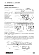
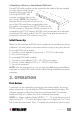
2. INSTALLATION Device Connection Standard Models (Model 521871): Determine the port number of each computer. For computers using a PS/2 mouse, connect the computer’s mouse and keyboard cables to the connectors marked with a mouse and keyboard, respectively, as shown. Repeat this step for PC-1 through PC-8. For computers using a serial mouse, connect the DB9-to-mini-DIN6 adapter (included with the switch) to the computer mouse port, then use PS/2 cables to connect the mouse to the KVM switch module.
To a PS/2 computer: Connect a PS/2 “Y” adapter, which comes with the unit, to the PS/2 port on the PC side, then use two mini-DIN6 male-to-male cables for the keyboard and mouse, as shown below. There are two mini-DIN6 female connectors on the PS/2 “Y” adapter marked for the keyboard and mouse. NOTE: Be sure not to swap the connections.
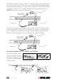
A Module as a Slave or a Stand-Alone KVM Switch A slave KVM switch module can be mounted to the inside of the rear uprights of a rack cabinet using the rear brackets (which come with all units except IKM001), with computer connectors facing to the rear, as well. NOTE: The connectors (keyboard and mouse) at the local port on the rear of the KVM module are not applicable when the module is connected to the TFT LCD drawer by the CEN36 connector.
Port A. If Port 1 is not selected, press and hold the “1” button on the console panel for two seconds to select Port A. The OSD menu and hotkeys are also available for computer selection. K/M Reset: K/M Reset solves most problems developed by the keyboard, the mouse, device replacement or a change of configuration. Press both the front-panel “1” and “2” buttons for two seconds to re-configure the whole system without turning off either the switch module or any computer.
and indicates the currently selected computer or operating status. A triangle mark (4) to the right of a name indicates the port is cascaded to a slave. The number to the left of the triangle mark shows the number of ports the slave has; e.g., 84 for an 8-port switch. The Enter key brings you one level down, and another screen pops up listing the names of the computers on that slave. The name of the slave will be shown at the upper-right corner of the OSD menu.
• • • • • • • Scan, the OSD displays the name of the selected computer. When Auto Scan detects any keyboard or mouse activity, it suspends the scanning until the activity stops, then resumes with the next computer in sequence. To abort Auto Scan, press the left Control key twice, or press any front-panel button. Scan Type and Scan Rate set the scan pattern. Scan Type (F4:More\Scan Type) determines if scanned computers must also be N-selected.
“Always On” means that the port number and the name of a selected computer and/or OSD status is displayed on the screen all the time. The non-volatile memory stores the CH Display setting. • Position: The position of the selected computer name and/or OSD status is displayed on screen during the operation. The choices are “Upper Left,” “Upper Right,” “Lower Left,” “Lower Right” and “Middle.
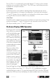
To select a computer by hotkey command, you need to know its port number, which is determined by the KVM switch module connection. For a computer connected to a master, its port is represented by the PC port label (1 – 8 or A – H). For a computer connected to a slave, two characters represent its port. The first character is the port number of the master unit (1 – 8); the second is the port number of the slave (1 – 8 or A – H). Note that only a master’s PC-1 through PC-8 ports can be connected to a slave.
NOTE: The master must have at least as many PC-x ports as the slave; e.g., if an IKM108D is the master, another IKM108D can be a slave, but not an IKM116D (see the reference on Page 5). The ports PC-1 through PC-8 can be connected to either a computer or a slave’s local (or console) port, as shown at right. The ports PC-A through PC-H can only be connected to computers. NOTE: Only a master’s PS/2 PC ports (not USB ports) can be connected to a slave’s local (or console) port for cascade application.
5. MULTI-ACCESS MODEL A multi-access console KVM switch (IKM2108D, IKM2116D) features a pair of console ports, facilitating access to multiple computers from both a local and a remote location. An example of the practicality of this feature is the ability to access all computers in a configuration from inside a server room when you need to physically access the computers — as when performing a software upgrade — while being able to manage the computers outside the server room for daily use.
6. SUN/MAC KEYBOARD MAPPING IGM108D and IGM116D models emulate a Sun keyboard and mouse when a computer is marked with a Sun in the OSD menu by function key F5. A Sun keyboard has more keys than a standard PS/2 keyboard. These extra keys are simulated by pressing the right Control key followed by one of the function keys on the PS/2 keyboard. For example, press the right Control key, then press function key F7 to activate Open for a Sun computer.
7. TROUBLESHOOTING Before troubleshooting any problem, ensure that all cables are properly connected and well seated. Check that keyboard and mouse cables are not swapped. Label and bundle the cables for each computer to avoid confusion when they’re connected to the KVM switch module. Problem Possible Cause Remedial Actions Nothing works. Bad connection at the CEN36 connectors. Push the assembled drawer and the KVM module box firmly together, leaving only 8 mm (5/16”) space in between.
Problem Possible Cause Remedial Actions Unable to Incorrect KVM operate USB-ready module. Sun server. Use only the hybrid PS/2 + USB KVM module. Keyboard error on Loose keyboard boot. connection. Make sure the keyboard cables are well seated. Alphabets on the TFT LCD display are blurred or have shadows. Set the VGA resolution of the computers to 1024 x 768 with “Large Font” for the best performance. Improper resolution settings. Master/slave does Improper not work. installation procedures.
Problem Possible Cause Remedial Actions Auto Scan doesn’t switch PCs; plus, the KVM switch module beeps occassionally and the red indicator flashes. All PCs are off or only one PC is turned on. Scan mode works only for powered computers. Turn on the computers. Scan Type is N-selected, but no powered PC is N-selected in the OSD. Press any front button to select a PC, and Auto Scan stops. Double OSD images in the cascade configuration. Improper slave connection procedure.
8. SPECIFICATIONS Model 521796: Standards • PS/2 General • PC connections: 8 • Console connections: 1 • PC port connectors: - Keyboard: 8 PS/2 - Mouse: 8 PS/2, serial (includes adapters for two ports) - Monitor: HD15 male • Console port connectors: keyboard, PS/2; mouse, PS/2; monitor, HD15 male • Computer selection: via buttons, hotkeys and Windows switching software client • Max.
Power Environmental • 12 V DC, 3 A (when connected to LCD drawer); 9 – 12 V DC, 500 mA (when not connected) • Power consumption: max. 500 mA • KVM module dimensions: 80 (H) x 404 (W) x 114 (D) mm (3.2 x 15.9 x 4.5 in.) • Weight: 18.8 kg (42.7 lbs.) • Operating temperature: 0 – 50°C (32 – 122°F) • Operating humidity: 0 – 95% • Storage temperature: -20 – 60°C (-4 – 140°F) • Storage humidity: 95% RH LCD Panel Specifications • Active display area: 304.1 x 228.1 (mm) • Pixel pitch (mm): 0.297 (H) x 0.
• Rear bracket and extension kit • Power adapter • 6 ft. (1.8 m) PS/2 3-in-1 cable • 6 ft. (1.8 m) USB 3-in-1 cable • Console quick installation guide • KVM Switch Module user manual Additional cables required (sold separately): • PS/2 3-in-1 KVM Cable, 6 ft. (1.8 m): 502535 • PS/2 3-in-1 KVM Cable, 10 ft. (3.0 m): 503303 • USB 3-in-1 KVM Cable, 6 ft. (1.8 m): 502242 • USB 3-in-1 KVM Cable, 10 ft. (3.
www.intellinet-network.com Are you completely satisfied with this product? Please contact your INTELLINET NETWORK SOLUTIONS™ dealer with comments or questions. Copyright © INTELLINET NETWORK SOLUTIONS All products mentioned are trademarks or registered trademarks of their respective owners.