
User guide

26
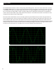
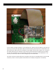
Rear View of the Module
If your module is acng erracally, or not working at all, make sure that all cables on the back are
securely connected. The top 40-pin cable connects the front panel board to the FPGA board. The
le-hand 10-pin cable connects the module to the Doepfer format power supply. The -12V pin of
the cable (usually the one marked in red) must be oriented towards the boom of the module.
The two-wire (red-black in the photo above) provides the +5V power to the FPGA board. If it is
correctly connected you will see a blue LED light up on the FPGA board.
The silver connector directly above the +5V power connector on the FPGA board is a mini-B USB
connector, which is used to update the rmware on the FPGA (see appendix C for details).