Modular LYNX Part I The Modular LYNX System ! ! ! ! ! ! ! ! ! ! ! Getting Started Connecting the LYNX System Mounting the LYNX System Powering the LYNX System The Communications Interface Configuring the Digital I/O The LYNX Control Module The LYNX Control Module (Combination) The Isolated Digital I/O Module The Differential Digital I/O Module The Combination Digital I/O Module
Table of Contents Section 1: Getting Started ................................................................................................................................................... 1-5 Section Overview ............................................................................................................................................................................ 1-5 Getting Started .........................................................................................................
List of Tables Table Table Table Table Table Table Table Table Table Table Table Table Table Table Table 4.1: 5.1: 5.2: 5.3: 5.4: 5.5: 5.6: 5.7: 5.8: 6.1: 6.2: 6.3: 6.4: 6.5: 6.6: Power Requirements ............................................................................................................................................... Wiring Connections: RS-232 Interface Single Control Module System .................................................................
Table Table Table Table Table Table Table Table Table Table Table Table Table Table Table Table Table Table Table Table Table Table Table Table Table Table 7.1: 7.2: 7.3: 7.4: 7.5: 7.6: 7.7: 7.8: 8.1: 8.2: 8.3: 8.4: 8.5: 8.6: 8.7: 9.1: 9.2: 9.3: 9.4: 9.5: 9.6: 10.1: 10.2: 10.3: 10.4: 10.5: Power Requirements for the LYNX Control Module ............................................................................................. LYNX Control Module LED Indicators ...........................................
Getting Started Section Overview The purpose of this section is to get you up and running quickly. This section will help you do the following: ! ! ! Connect power to the LYNX Control Module. Connect and establish communications in single mode. Write a simple test program.
U s e r P r o v i d e d To o l s a n d E q u i p m e n t N e e d e d ! ! ! ! ! ! ! ! Serial Cable IM483 or equivalent step motor driver ISP200-4 or equivalent power supply M-22XX or equivalent stepping motor Wire Cutters/Strippers 22 gauge wire for logic level signals 18 gauge wire for power supply and motor wiring PC with a free serial port (COM 1 or 2) Connecting the Power Supply 1. 2. 3.
NOTE: If the sign-on message does not appear, check the “Connected/Disconnected” tab at the bottom of the Terminal Window. If “Disconnected” is displayed, double click it to “Connect”. Detailed instructions for the IMS Terminal software can be located in Part III Software Reference of this manual. Te s t i n g t h e LY N X S e t u p Two basic instructions for communicating with a control module are SET and PRINT. The SET instruction is assumed and can be left off when communicating in ASCII mode.
Once you have been able to move the motor, the next step is to write a simple program to illustrate one of the dynamic features of the LYNX: the ability to convert motor steps to a dimension of linear or rotary distance. Let’s begin by discussing the relationship between the MUNIT variable and user units. Typically when we perform a move we want to know the distance of that move in a familiar unit of measurement. That means translating motor steps to the desired unit of measurement.
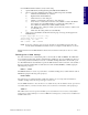
C o n n e c t i n g t h e LY N X S y s t e m Section Overview Each module of the LYNX System is a closed unit with a header of pins and locking tabs to connect it to another module in the system. Optional I/O modules are connected on the RIGHT side of the Control Module. This section covers: ! ! Removing the End Plates. Connecting/Disconnecting System Modules. Connecting the System 1. 2. 3. 4. 5. Remove the end plate(s) [A] from the Control Module.
Section 3 M o u n t i n g t h e LY N X S y s t e m Section Overview This section covers the two basic methods of mounting the LYNX System. ! ! Panel Mount. DIN Rail Mounting Option. Panel Mount Using the panel mount option, the LYNX is designed to use #10 hardware (not included). Details such as screw length and threads are dependent on your overall system design. Din Rail Mounting Option A DIN Rail mounting kit (IMS P/N LX-DB100-000) may be purchased as an option to your LYNX System.
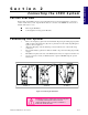
DIN Rail Bracket B DIN Rail 3. Holding the LYNX System at an angle away from you, lower the upper slot of the DIN rail attachment onto the top edge of the DIN rail. Snap LYNX system into place. Figure 3.2. 4. Insert #6 X .250 L set screw (provided) into the TOP threaded insert located between the #6 screws on each end plate. Figure 3.3. Tighten until 12-14 in/ oz. This will keep the system from sliding on the DIN rail. C LYNX System A C B Figure 3.
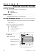
Section 4 P o w e r i n g t h e LY N X S y s t e m Section Overview This section covers the two basic power configurations for your LYNX System. ! ! ! Basic rules of wiring and shielding. LYNX Control Module with IMS Drivers. LYNX Control Module as Stand-alone or with Optional I/O Module. Wiring and Shielding Noise is always present in a system that involves high power and small signal circuitry.
A0 A1 A2 PT HI UG 21 22 23 24 25 26 1 2 3 4 5 6 1 2 3 4 5 6 In this example, power is connected to the LYNX Control Module via connector P1. All optional plug-on modules are then powered from the LYNX Control Module. In this configuration, pins 5 and 6 on connector P2 of the Control Module become +5VDC (150mA, internally limited) regulated outputs. If an encoder is to be used in the system, it may be powered via these pins. Below is a table of recommended power supply specifications for each IMS drive.
Stand-alone or with Optional I/O Modules +12 to +75VDC Supply A +12 to +75VDC unregulated supply connected to P1 provides power to the LYNX Control Module and any optional I/O modules. As in the LYNX Controller with Driver (s) Configuration, pins 5 (Ground) and 6 (+5VDC) on connector P2 of the Control Module becomes a +5VDC (150mA, internally limited) regulated output.
Modular LYNX System Power Requirements Pow er Requirements and Specifications Input Voltage +12 to +75 VDC Unregulated or +5VDC ±5% 250mA (5VDC input) Input Current 165mA (+12VDC Input)* 95.0mA (+48 VDC Input)* 84.
Section 5 The Communications Interface Section Overview The LYNX Control Module features two communication interfaces: RS-232 and RS-485. For both channels, the BAUD rate is software configurated, using the BAUD variable, to 4800, 9600, 19200 or 38400 bits/sec. The factory default is set to 19200 bits/sec. Default data settings are 8 data bits, 1 stop bit and no parity. A host computer can be connected to either interface to provide commands to the control module or to multiple control modules in a system.
Modular LYNX System RS-232 Interface: Wiring And Connections LYNX Control Module 25 Pin Serial Port on PC 9 Pin Serial Port on PC Receive Data (RX) P i n 12 Transmit Data (TX) Pi n 2 Transmit Data (TX) Pi n 3 Transmit Data (TX) P i n 13 Receive Data (RX) Pi n 3 Receive Data (RX) Pi n 2 Communications Ground Pin 11 Communications Ground Pi n 7 Communications Ground Pi n 5 Table 5.
name, to identify it in the system. This can be done using configuration switches A0-A2, or by using the software command SET DN. For example, to set the name of a controller to "A" you would use the following command: SET DN = "A". The factory default name is "!".
Modular LYNX System RS-232 Interface: Wiring And Connectionsfor Multiple LYNX Nodes Host Control Module Control Module #1 Control Module #n Receive Data (RX-) Pi n 7 Transmit Data (TX-) Pi n 9 Transmit Data (TX-) Pi n 9 Receive Data (RX+) Pi n 8 Transmit Data (TX+) P i n 10 Transmit Data (TX+) P i n 10 Transmit Data (TX-) Pi n 9 Receive Data (RX-) Pi n 7 Receive Data (RX-) Pi n 7 Transmit Data (TX+) P i n 10 Receive Data (RX+) Pi n 8 Receive Data (RX+) Pi n 8 Communications Groun
Connecting the RS-485 Interface Single Controller System In a Single Controller System, the RS-485 interface option would be used if the Control Module is located at a distance greater than 50 feet from the Host PC. Since most PC’s do not come with an RS-485 board preinstalled, you will have to install an RS-485 board in an open slot in your PC, or purchase an RS-232 to RS485 converter, such as the CV-3222 sold by IMS, to use this connection interface.
Modular LYNX System N NOTE: The HOST switch MUST be off to communicate with the Control Module in a Single Controller System using the RS-485 Interface. Multiple Controller System When using the RS-485 Party Mode Address Configuration Sw itches interface in a Multiple Controller System, the Host PC as well Address A2 A1 A0 as all of the control modules N one OFF OFF OFF communicate on the RS-485 interface.
RS-485 Interface: Wiring And Connectionsfor Multiple LYNX Nodes RS-232 to RS-485 Converter Control Module #1 Control Module #n Receive Data (RX-) Transmit Data (TX-) Pi n 9 Transmit Data (TX-) Pi n 9 Receive Data (RX+) Transmit Data (TX+) P i n 10 Transmit Data (TX+) P i n 10 Transmit Data (TX-) Receive Data (RX-) Pi n 7 Receive Data (RX-) Pi n 7 Transmit Data (TX+) Communications Ground Receive Data (RX+) Pi n 8 Communications Ground Pin 11 Receive Data (RX+) Pi n 8 Communications
There are three modes of operation for the LYNX control module. These are Immediate Mode, Program Mode, and EXEC Mode. Immediate Mode In this mode, the control module responds to instructions from the user that may be a result of the user typing instructions directly into a host terminal, or of a user program running on the host which communicates with the control module. Program Mode The second mode of operation of the control module is Program Mode. All user programs are written in this mode.
ASCII Mode Special Command Characters Character Action at MicroLYNX E sca p e K e y Terminates all active operations and all running programs. <^C> Ctrl+C Keys Terminates all active operations and all running programs, forces a reset of the MicroLYNX. B a cksp a ce K e y or Carriage Return or Line F eed Moves the cursor back one in the buffer to correct a typing error. Depending on the mode, either Single or Party. is not necessary in Single Mode communications.
Configuring the Digital I/O Section Overview This section covers the usage of the Isolated Digital and High Speed Differential I/O Modules which are available on the LYNX System. ! ! System I/O Availability by Module.
The Isolated Digital I/O The LYNX CM100 Control Module has a standard set of twelve +5 to +24VDC I/O lines and the LYNX CM200 Combination Control Module has a standard set of six +5 to +24VDC I/O lines. These I/O lines may be programmed individually as either general purpose or dedicated inputs or outputs, or collectively as a group. The Isolated Digital I/O may be expanded to a maximum of twenty-four (24) lines on the CM100 and a maximum of eighteen (18) lines on the CM200.
The IOS variable has three parameters when used to configure the isolated digital I/O. These are: 1] I/O Line Type: Specifies the the type of I/O that the line or group will be configured as, i.e. general purpose or dedicated function. I/O Line Function: Either an input or an output. Active State: Specifies whether or not the line will be active HIGH or active LOW. 2] 3] The default configuration of the standard I/O set is: 0,0,1.
Configuring an Input LYNX Control Module Figure 6.2 below illustrates the Input Equivalent Circuit of the Isolated I/O being used with a switch. To illustrate the usage of an input you will go through the steps to configure this switch to start a simple program at Line 1000 to index a motor 200 user units. First you must configure the I/O Line 21 as a “GO” input: 4.
Figure 6.3 illustrates the Output equivalent circuit of the Isolated I/O. When used as an output the I/O line is able to sink 350mA continuous for each output, or a total of 1.5A for the entire I/O Group. See Section 9: The Isolated Digital I/O Module for detailed specifications. In the usage example we will use an LED on I/O Line 31 for the load. We will use the same program from the input example, only we will use the output to light the LED while the motor is moving.
Read/Write an I/O Group When using the IO variable to read the state of a group of inputs/outputs, or write to a group of outputs you would first want to configure the entire I/O group to be general purpose inputs or outputs using the IOS variable. In this case the response or input won’t be a logic state of 1 or 0, but rather the decimal equivalent (0 to 63) of the 6 bit binary number represented by the entire group.
The Clock Interface Quadrature The LYNX has four clock pairs that are used by the high speed I/O. One of these, clock pair 11 and 12, is fixed as an output and is used internally to provide step clock and direction pulses to Step Clock and Direction outputs located on Connector P1 of the LYNX Controller. The step clock output increments CTR1 (Counter 1). CTR1 may be read from or written to by software instructions in either program or immediate mode.
C o n f i g u r i n g T h e D i f f e r e n t i a l I / O - T h e I O S Va r i a b l e The high speed differential I/O is configured by means of the IOS variable, and is used in the the same fashion in which the isolated I/O is configured. The main difference lies in that there are three additional parameters which need to be set in configuring the triggering, clock type, and ratio mode setting.
IOS 13 = 3, 0, 1, 0, 1, 0 IOS 14 = 4, 0, 1, 0, 1, 0 IOS 15 = 5, 0, 1, 0, 1, 0 IOS 16 = 6, 0, 1, 0, 1, 0 IOS 17 = 7, 0, 1, 0, 1, 0 IOS 18 = 8, 0, 1, 0, 1, 0 Setting the Digital Input Filtering for the Differential I/O User definable Digital filtering makes the LYNX well suited for noisy industrial environments. The filter setting is software selectable using the IOF Variable with a minimum guaranteed detectable pulse width of 18 microseconds to 2.3 milliseconds.
In the Equivalent Circuit in Figure 6.7 an Output is being used as Step or Direction on a driver. For the configuration example, use I/O line 13 for the output. Since by default the line is a quadrature input we must configure it to be a Step/Direction Output by setting the IOS Variable to the following: IOS 13 = 3, 1, 0, 1, 2, 0 This breaks down as: IOS 13 - Identifies the line being configured as 13. 3 - Sets the I/O Type to Clock 2A (default). 1 - Sets it as an output. 0 - Sets Logic at Low True.
DIR+ +5VDC OUTPUT DIR- 21 DIR+ 22 SCK- 23 SCK+ 24 GND 25 +5V 26 RX- 31 RX+ 32 TX- 33 TX+ 34 CGND 35 RX 36 TX IG V+ TM 1 2 3 4 5 6 GND 31 32 33 34 35 36 Differential/O MODULE SCLK+ 21 22 23 24 25 26 HSIO 1313+ 1414+ ENCODER Channel AChannel A+ Channel BChannel B+ TM A0 A1 A2 PT HI UG 1 2 3 4 5 6 1 2 3 4 5 6 By printing the variable CTR2 (CTR2 = EUNIT X POS) we can view the distance the motor has traveled in raw encoder counts, or by printing POS you can see the dista
by a motor mounted encoder. The actual count of encoder pulses received by the Control Module is maintained by the register CTR2, (if the encoder is connected to I/O line pair 13 &14) with the EUNIT variable scaling it to user units. Example: User Unit (POS) = CTR2 ÷ EUNIT where EE (Encoder Enable) Flag = TRUE(1) When using the EUNIT scaling factor it is important to understand that you MUST set the EUNIT variable AND the MUNIT variable to the same scaling factor for accurate position monitoring.
1 2 3 4 5 6 SCK- 23 SCK+ 24 GND 25 +5V 26 RX- 31 RX+ 32 TX- 33 TX+ 34 CGND 35 RX 36 TX IG V+ TM 1 2 3 4 5 6 GND 31 32 33 34 35 36 Modular LYNX System 21 22 Differential/O MODULE DIR+ +5VDC OUTPUT DIRDIR+ ENCODER Channel A Channel B TM SCLK+ 21 22 23 24 25 26 1 2 3 4 5 6 A0 A1 A2 PT HI UG HSIO 13+ 14+ 1313+ 1414+ 1515+ Encoder or Pulse Generator 1616+ 1717+ 1818+ GD Stepping Motor +5VDC Opto Supply Z N429D G P59627A Step Clock Input ZN429D GP59627A Direction Inpu
RATIOE = 1 ‘Set RATIO variable to .5 for the RATIO = .
The LYNX Control Module (LX-CM100-000) Section Overview This section will cover: ! ! ! ! ! Hardware Specifications ! Environmental Specifications ! Mechanical Specifications ! Power Requirements Connection Overview LED Indicators Pin Assignments Switch Assignments Hardware Specifications Environmental Specifications Ambient Operating Temperature .............................................. 0 to +50 degrees C Storage Temperature ................................................................
Power Requirements Pow er Requirements and Specifications Input Voltage +12 to +75 VDC Unregulated or +5VDC ±5% 250mA (5VDC input) Input Current 165mA (+12VDC Input)* 95.0mA (+48 VDC Input)* 84.5mA (+75VDC Input)* *I/O and +5VDC output unloaded (Control Module Only) Output Voltage +5VDC ±5% Output Current 150mA (Internally Limited Table 7.
Modular LYNX System LED Indicators LED Color Meaning Green Power On Red System or software fault detected. The user can choose to enable or disable the indicator by setting the FAULT flag. FAULT=TRUE (1) will cause the LED to illuminated whenever an ERROR occurs. Table 7.2: LYNX Control Module LED Indicators Pin Assignment and Description P1 - Tw o Position Screw Lock Terminal: Input Pow er Connection Pin # Function Description 1 Power Ground Power ground for the unregulated power supply.
P3 - 13 Position Removeable Terminal Connector: Isolated Digital I/O Pin # Function Description 1-8 I/O Group 20 Lines 21 - 26 Signals are individually programmable as inputs or outputs (see description of theIOS command in the Part 3: Software Reference of this manual). Inputs are CMOS logic level compatible and can accept inputs to 28 volts. Noise rejection is available via digital filtering. Outputs are open drain. I/Os each have individually switchable 7.5 Kohm pull up resistors to 5VDC.
T h e LY N X C o n t r o l M o d u l e ( C o m b i n a t i o n ) Section Overview The Control Module (Combination) (IMS Part # LX-CM200-000) offers the user of purchasing a LYNX Control Module with 3 differential I/O Channels and 6 Isolated I/O lines instead of the standard 2 Isolated I/O groups.
Power Requirements Pow er Requirements and Specifications Input Voltage +12 to +75 VDC Unregulated or +5VDC ±5% 250mA (5VDC input) Input Current 165mA (+12VDC Input)* 95.0mA (+48 VDC Input)* 84.5mA (+75VDC Input)* *I/O and +5VDC output unloaded (Control Module Only) Output Voltage +5VDC ±5% Output Current 150mA (Internally Limited Table 8.
Modular LYNX System LED Indicators LED Color Meaning Green Power On Red System or software fault detected. The user can choose to enable or disable the indicator by setting the FAULT flag. FAULT=TRUE (1) will cause the LED to illuminated whenever an ERROR occurs. Table 8.2: LYNX Control Module LED Indicators Pin Assignment and Description P1 - Tw o Position Screw Lock Terminal: Input Pow er Connection Pin # Function Description 1 Power Ground Power ground for the unregulated power supply.
P3 - 13 Position Removeable Terminal Connector: Combination I/O Pin # Function 1 I/O 13- Pins 1 and 2 are the differentially buffered signal for group 10, I/O 13.This channel is configured by means of the IOS Instruction. For usage details see Section 6: Configuring the Digital I/O. 2 I/O 13+ See description above. 3 I/O 14- Pins 3 and 4 are the differentially buffered signal for group 10, I/O 14.This channel is configured by means of the IOS Instruction.
The Isolated Digital I/O Module Section Overview The Isolated I/O Module (IMS Part # LX-DI100-000) offers the user an additional 12 Isolated +5 to 24VDC General Purpose I/O lines in two groups of six each (Groups 40 and 50) for a total of 24 individually programmable I/O when used with the LYNX CM100 Control Module or 18 when used with the CM200 Combination Control Module.
Connection Overview 1 2 3 4 5 6 TM +5V Pullup Enable Switches for I/O Group 40 41 42 Group 40 Isolated I/O 43 44 45 46 P1 51 52 Group 50 Isolated I/O 53 54 55 56 Isolated Ground IG 1 2 3 4 5 6 ISOLATED I/O MODULE 41 42 43 44 45 46 51 52 53 54 55 56 +5V Pullup Enable Switches for I/O Group 50 Figure 9.
Group 40 I/O Pull-Up Sw itches: Can Be Changed at any Time, Usable for Exercising Inputs Sw itch # Function Description 1-6 Individual Switches for I/O Group 40 Pull-Ups. When this switch is on, the I/O is pulled up through an internal 7.5 Kohm resistor to 5VDC. Can be used to simulate the activation of an input while testing system software.. Table 9.
Input Filtering User definable Digital filtering makes the LYNX well suited for noisy industrial environments. The filter setting is software selectable using the IOF Variable with a minimum guaranteed detectable pulse width of 18 microseconds to 2.3 milliseconds. IOF Filter Settings for the General Purpose Isolated I/O IOF= ( = 0-7) Filter Setting Cutoff Frequency 0 27.5 kHz 18 microseconds 1 13.7 kHz 36 microseconds 2 6.89 kHz 73 microseconds 3 3.44 kHz 145 microseconds 4 1.
The Differential Digital I/O Module Section Overview A LYNX system may contain an optional Differential I/O Module (IMS Part# LX-DD100-000) which provides six (6) high speed differential I/Os. These I/Os can be used as clock inputs or outputs or general purpose I/O. Along with the differential motion I/Os (P1, pins 1 – 4) of the LYNX Control Module, these I/O make up the Group 1 signal set. Each signal pair is a 0 to 5VDC input or output.
Connection Overview TM DIFFERENTIAL I/O MODULE 1313+ 1414+ 1515+ 16- Group 10 High Speed I/O 16+ P1 1717+ 1818+ PGND Ground Figure 10.2: High Speed Differential I/O Module Connection Overview Power Requirements Power is supplied through the LYNX Control Module. High Speed Differential I/O Pow er Requirement Input Voltage to LYNX Control Module Current Requirement for Module +5VDC 50mA +12 VDC 28mA +48VDC 8mA +75VDC 5mA Table 10.
P3 - 13 Position Removeable Terminal Connector: High Speed Differential I/O Module Pin # Function Description 1 I/O 13- Pins 1 and 2 are the differentially buffered signal for group 10, I/O 13. This channel is configured by means of the IOS Instruction. This channel is fixed as clock #2 and associated with Counter 2 (CTR2). For usage details see Section 6: Configuring the Digital I/O. 2 I/O 13+ See description above.
High Speed Differential I/O Module +5VDC Edge Edge Detect Logic Polarity Level 10kΩ + Digital Filter Differential Encoder 3.3kΩ Input (+) 4.3V Channel A (+) Input (-) - 1.4V 4kΩ 20kΩ Channel A (-) Channel B (+) Group Filter Setting Channel B (-) Index (+) Index (-) Figure 10.3: LYNX Differential I/O Input Equivalent Circuit Input Filtering User definable Digital filtering makes the LYNX well suited for noisy industrial environments.
Modular LYNX System Output Specifications High Speed Differential I/O Output Specifications N o L o ad 6mA Load Output Voltage - Logic 0 0.5V 0.8V Output Voltage - Logic 1 4.5V 4.2V Short Circuit Current 250mA Max. High Speed Differential I/O Module Table 10.5: LYNX Differential I/O Output Specifications +5VDC 10kΩ Secondary Drive 3.3kΩ Output (+) Step Clock Clock User Defined Function Output (-) 4kΩ 20kΩ IOS Output (+) Direction Figure 10.
Intentionally Left Blank 1 - 56 Modular LYNX System 12.05.