
- IMS Motion Detector Product Operating Instructions


A-3
Appendices
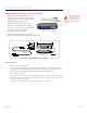
WARNING! DO NOT
connect or disconnect
the MD-CC300-000
Communications Converter
Cable from MForce while power is
applied!
Ap pe nd ix C
Optional Prototype Development Cables
MD-CC300-000: USB to SPI Parameter Setup Cable
The MD-CC300-000 USB to SPI Parameter Setup
Cable provides a communication connection between
the 10-pin connector on some Microstepping MForce
PowerDrives and the USB port on a PC.
IMS SPI Interface Software communicates to the
Parameter Setup Cable through the PC's USB port.
The Parameter Setup Cable interprets SPI commands
and sends these commands to the MForce
PowerDrive through the SPI interface.
Supplied Components: MD-CC300-000 Parameter
Setup Cable, USB Cable, USB Drivers, IMS SPI Interface Software.
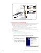
Adapter Cables
Parameter Setup Cable and Adapters
The optional 12.0' (3.6m) parameter setup cable part number MD-CC300-000 facilitates communica-
tions wiring and is recommended with first order. It connects from the P2 connector to a PC's USB port.
Models with the 12-pin pluggable locking wire crimp require adapter MD-ADP-1723C.
Prototype Development Cable
For testing and development using the 12-pin pluggable locking wire crimp, the 12.0" (30.5cm) prototype
development cable plugs into the MD-ADP-1723C adapter and has flying leads for connection to the user
interface. Part number ADP-3512-FL.
See Figure A.3 on the following page for dimensional and connection information.
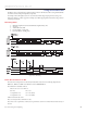
Figure A.1: MD-CC300-000
10 Pin Connector
Cable Length 6.0 ft (1.8 m)
MD-CC300-000
USB to SPI Parameter Setup Cable
www.imshome.com
USB Cable
Length 6.0 ft (1.8 m)
1.0 in
(25.0 mm)
3.75 in
(95.0 mm)
0.875 in
(22.0 mm)
USB
To MForce
To PC USB
Figure A.2: MD-CC300-000 Mechanical Specifications