Excellence in Motion TM DSP-402 APPLICATION GUIDE TM CANopen FORCE TM DRIVE CANopen
MDrivePlus CANopen Change Log Date Revision Changes 10/06/2006 R100606 Initial Release 12/20/2006 R122006 Added newly supported objects to DSP-402 Implementation 02/05/2007 R020507 Added new object support, broke out DSP 402 to separate document. The information in this book has been carefully checked and is believed to be accurate; however, no responsibility is assumed for inaccuracies. Intelligent Motion Systems, Inc.
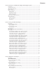
Contents Section 1: Introduction to the MDrivePlus CANopen DSP-402 Implementation...................................3 Introduction...................................................................................................................................3 CAN Message Format....................................................................................................................3 MDrivePlus Architecture..........................................................................................
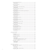
Object 2006h: Input Filter Time (ms)..........................................................................................19 Object Description..................................................................................................................19 Entry Description....................................................................................................................19 Object 2010h: Analog Input......................................................................................
Entry Description....................................................................................................................32 Data Description.....................................................................................................................32 Object 6502h — Supported Drive Modes....................................................................................32 Object Description...................................................................................................
Entry Description....................................................................................................................50 Object 6066h — Following Error Timeout..................................................................................50 Object Description..................................................................................................................50 Entry Description.....................................................................................................
List of Figures Figure 1.1: Message Format............................................................................................................3 Figure 1.2: MDrivePlus Architecture..............................................................................................3 Figure 1.3: Functional Architecture................................................................................................4 Figure 1.4: MDrivePlus CANopen Object Dictionary................................................
This Page Intentionally Left Blank vi
Excellence in Motion TM DSP-402 Application guide Section 1: Introduction to the MDrivePlus CANopen DSP-402 Implementation Section 2: Manufacturer Specific Objects Section 3: Accessing the MDrivePlus CANopen Section 4: Device Control Section 5: Modes of Operation Section 6: Profile Position Section 7: Homing Mode Section 8: Position Control Function Section 9: Profile Velocity Section 10: Optional Application FE
Page Intentionally Left Blank MDrivePlus CANopen R020507
Section 1 Introduction to the MDrivePlus CANopen DSP-402 Implementation Introduction This document describes the Operational Modes and Objects utilized by the MDrivePlus CANopen. The MDrivePlus uses the CiA DSP402 protocol as described the the CiA document CANopen Device Profile for Drives and Motion Control V2.0B. CAN Message Format The MDrivePlus is compliant with CAN 2.0B Active Specification. The Data Packets follow the message format shown in Figure 1.1.
Device Control The starting and stopping of the drive and several mode specific commands are executed by the state machine. Modes of Operation The operation mode defines the behavior of the drive. The following modes are defined in this profile: Homing Mode This chapter describes the various methods to find a home position (also: reference point, datum, zero point). Profile Position Mode The positioning of the drive is defined in this mode.
Trajectory Generator The chosen operation mode and the corresponding parameters (objects) define the input of the Trajectory Generator. The Trajectory Generator supplies the control loop(s) with the demand values. They are generally mode specific. Each Mode may use its own Trajectory Generator. A general description of its functionality is given in Section X, which is related to the Profile Position Mode.
Object Formatting This manual will display the Object and Entry data using the model detailed below. Object Description Index Name XXXXh Object Code Index Name VAR Data Type I/U Index The Index is the hexadecimal number that represents the index number of the object in the CANopen Object Dictionary. With the exception of IMS Manufacturer specific objects these are defined in CiA Device Profile for Drives and Controls DSP402. The applicable objects are defined in this document as well.
PDO Mapping Describes whether (Yes) or not (No) the Index may be mapped to a PDO (Process Data Object). If yes it may be mapped to a PDO, if No the Object must be accessed using SDO (Service Data Objects). Category M........................................................................................Mandatory O........................................................................................... Optional Range The range of the Index will be expressed as a ± Integer or Unsigned.
Page Intentionally Left Blank MDrivePlus CANopen R020507
Section 2 Accessing The MDrivePlus CANopen Introduction The access from the CAN network to the drive is done through data objects. Process Data Object (PDO) PDOs are messages in an unconfirmed service. They are used for the transfer of real-time data to and from the drive. The transfer is fast, because it is performed with no protocol overhead what means to transport eight application data bytes in one CAN-frame. The PDOs correspond to entries in the Object dictionary. PDO Attributes 1. 2. 3. 4. 5. 6.
PDO Mapping The MDrivePlus CANopen allows you to map objects to PDOs to reduce the transfer application data more efficiently. By using the PDO the user can map a PDO to multiple objects (8 Data Bytes max.) The example will show RPDO 1400h mapped to Control Word (6040h) and Target Position (607Ah).
PDO Objects Consumer PDO1 (RPDO1) 1400h (Object Description) Index Name Object Code Data Type Category 1400h Receive PDO1 Parameter Record PDO Communications Parameters Mandatory Consumer PDO1 (RPDO1) 1400h (Entry Description) Sub-Index Description Category Access 00h Highest Supported Sub-Index Mandatory R/W Mfg.
Consumer PDO2 (RPDO2) 1401h (Object Description) Index Name Object Code Data Type Category 1401h Receive PDO2 Parameter Record PDO Communications Parameters Optional Consumer PDO2 (RPDO2) 1401h (Entry Description) Sub-Index Description Category Access 00h Highest Supported Sub-Index Mandatory R/W 02h 01h COB-ID used by PDO Mandatory R/W 0000 0300h or 8000 0000h + NODE ID 02h Transmission Type Mandatory R/W 255d 03h Inhibit Time Optional R/W 04h Value Range Default Reserve
Consumer PDO3 (RPDO3) 1402h (Object Description) Index Name Object Code Data Type Category 1402h Receive PDO3 Parameter Record PDO Communications Parameters Optional Consumer PDO3 (RPDO3) 1402h (Entry Description) Sub-Index Description Category Access 00h Highest Supported Sub-Index Mandatory R/W 02h 01h COB-ID used by PDO Mandatory R/W 0000 0400h or 8000 0000h + NODE ID 02h Transmission Type Mandatory R/W 255d 03h Inhibit Time Optional R/W 04h Value Range Default Reserve
Producer PDO1 (TPDO1) 1800h (Entry Description) Sub-Index Description Category Access 00h Highest Supported Sub-Index Mandatory R 02h 01h COB-ID used by PDO Mandatory R/W 4000 0180h + NODE ID 02h Transmission Type Mandatory R/W 255d 03h Inhibit Time Optional R/W 04h Value Range Default Reserved 05h Event Timer Optional R/W 0d 1A00h (Object Description – Mapping Parameters) Index Name Object Code Data Type 1A00h Transmit PDO1 Mapping Record PDO Mapping Category Mandato
1A01h (Object Description – Mapping Parameters) Index Name Object Code Data Type Category 1A01h Transmit PDO2 Mapping Record PDO Mapping Conditional if 1801h is implemented 1A01h (Entry Description – Mapping Parameters) Sub-Index Description Category Access Value Range Default 00h Highest Supported Sub-Index Mandatory R/W 02h 01h 1st Application Object Mandatory R/W 6041 0010h 02h 2nd Application Object Optional R/W 6061 0008h 03h 3rd Application Object Optional R/W Mfg.
1A02h (Entry Description – Mapping Parameters) 16 Sub-Index Description Category Access Value Range Default 00h Highest Supported Sub-Index Mandatory R/W 02h 01h 1st Application Object Mandatory R/W 6041 0010h 02h 2nd Application Object Optional R/W 6064 0010h 03h 3rd Application Object Optional R/W Mfg. Specific 04h 4th Application Object Optional R/W Mfg. Specific 05h 5th Application Object Optional R/W Mfg. Specific 06h 6th Application Object Optional R/W Mfg.
Section 3 Manufacturer Specific Objects Introduction The objects detailed in this section are IMS manufacturer specific configuration objects to conFigure : • I/O Type • Run/Hold Current • Factory Configuration Accessibility Codes R — Read W — Write S — Storable to Nonvolatile Memory (NVM) K — Key Required Object 2000h: I/O Discretes (Config) Object Description Index Name 2000h Object Code I/O Discretes Data Type VAR Unsigned 8 Entry Description Sub-Index Description Category Access PDO
Object 2002h: I/O Discretes (Config) Object Description Index Name 2002h Object Code Data Type Config Input Switches VAR Unsigned 8 Entry Description Sub-Index Description Category Access PDO Mapping Value Range Default 01h ConFigure I/O as Home Mandatory R/W No 0x00 — 0xFF 0x00 (1 = Selects I/O# as the Home Switch) 02h ConFigure I/O as Positive Limit Mandatory R/W No 0x00 — 0xFF 0x00 (1 = Selects I/O# as the Positive Limit) 03h ConFigure I/O as Negative Limit Mandatory R/W N
Object Description Index 2004h Name Object Code Input Filter Mask Data Type VAR Unsigned 8 Entry Description Sub-Index Description Category Access PDO Mapping Value Range Default 01h Input Filter Mask Optional R/W No 00h – FFh 01h 02h Input Filter Mask Optional R/W No 00h – FFh 02h 03h Input Filter Mask Optional R/W No 00h – FFh 04h 04h Input Filter Mask Optional R/W No 00h – FFh 08h 05h Input Filter Mask Optional R/W No 00h – FFh 10h 06h Input Filter Mask
Object 2010h: Analog Input Object Description Index 2010h Name Object Code Analog Input Data Type VAR See Entry Desc.
Object 2031h: Unit Options (Encoder Enable, Capture In/Trip Out) Object Description Index Name 2031h Object Code Unit Options VAR Data Type Unsigned 8 Entry Description Access PDO Mapping R/W/S Range No Default 0/1 0 Note: Encoder functions only apply to the MDrive products. The MForce products do not have closed loop capability.
Entry Description Sub-Index Description 01h Category Access PDO Mapping Value Range Enable Capture Position R/W Yes 0/1 02h Enable Capture Input Flag R/W No 0/1 03h Capture Input Filter R/W No 04h Capture In Position R/W No Default Data Type Object 2204h: Run Current Percent Object Description Index Name 2204h Object Code Run Current % VAR Data Type Unsigned 8 Entry Description Access PDO Mapping R/W/S Range No 1 - 100 Default 25 Run Current % By Device 2204h MDriv
Hold Current % By Device 2205h MDrivePlus (All) MForce MicroDrive (Amps RMS) 10 MDrive Range 0 To 100% 20 30 Actual Current Not required as Motor is appropriately sized to the device. 40 50 MForce PowerDrive (Amps RMS) 0.3 0.5 0.6 1.0 0.9 1.5 1.2 2.0 1.5 2.5 1.8* 3.0 70 2.1 3.5 80 2.4 4.0 90 2.7 4.5 100 3.0 5.0 60 Shaded Area Reserved for Future Use *HC=67 for maximum 2.
Entry Description Access R/K PDO Mapping No Range Default N/A Factory Object 5002h: ASCII Serial Number The following object is set at the factory, and is not user configurable. It can be read by the user in the event that the contained data is needed for technical or application support. Object Description Index 5002h Name Object Code ASCII Ser. No.
Section 4 Device Control Device Control Controlword 6040h The device control function block controls all the functions of the MDrivePlus CANopen and is divided into to sections: 1. Control of the State Machine DEVICE CONTROL Profile Position 2. Operation Mode State Machine Profile Velocity Control and Status words Controlword (Object Index 6040h) controls the state and operation modes of the MDrivePlus CANopen. Statusword (Object Index 6041h) returns the status of the MDrivePlus CANopen.
State Machine Transitions Transition Number From State To State Not Ready To Switch On 0 Start 1 Not Ready To Switch On Switch On Disabled 2 Switch On Disabled Ready to Switch On 3 Ready to Switch On Switched On 4 Switched On Operation Enable 5 Operation Enable Switched On 6 Switched On Ready to Switch On 7 Ready to Switch On Switch On Disabled 8 Operation Enable Ready to Switch On 9 Operation Enable Switch On Disabled 10 Switched On 11 Operation Enable 12 13 14 15 16
Controlword 6040h Power Disabled Fault 13 Fault Reaction Active Start 0 14 Not Ready to Switch On Fault 1 15 Switch On Disabled 2 SUPPORT FOR FAULT STATES UNDER DEVELOPMENT 7 Ready To Switch On 9 8 3 6 Internal Event 10 12 Switched On 4 5 11 16 Operation Enable Quick Stop Active Power Enabled Statusword 6041h Figure 4.
Object 6040h — Controlword Ths controlword is a mandatory, unsigned 16 bit number containing bits for controlling the state and operating modes for the MDrivePlus CANopen.
Object 6041h — Statusword The Statusword is a read-only object that indicates the current state of the drive, no bits are latched. Statusword consists of bits for: The current state of the drive. The operating state of the mode. Manufacturer Specific options.
Bit 4: Voltage Enabled The Disable Voltage request is active when the voltage_disabled bit is cleared to 0. Bit 5: Quick Stop Active When reset, this bit indicates that the drive is reacting on a quick stop request. Bits 0, 1 and 2 of the statusword must be set to 1 to indicate that the drive is capable to regenerate. The setting of the other bits indicates the status of the drive (e.g. the drive is performing a quick stop as result of a reaction to a non-fatal fault.
Section 5 Modes of Operation Object 6060h — Modes of Operation The performance of the MDrivePlus CANopen depends on the activated Modes of Operation. It is not possible to operates the modes in parallel. The user must select a mode to operate in. An example of exclusive functions are Profile Velocity and Profile Position modes. The MDrivePlus allows the user to switch dynamically from operation mode to operation mode.
Mode of Operation (6060h) 8...127 7 6 5 4 3 2 1 0 -1...-128 M . uf an ile on fic ti si Po e od i ec Sp ed rv se Re of Pr M ty ci e od e od es od M M M on e od M ti si Po e od lo Ve M ue rq To ty ci ile ile lo Ve of Pr of Pr g in om ed at ed rv se Re H ol rp te In ed rv se Re e od M Gray Text modes unsupported by MDrivePlus CANopen Figure 5.
31 MSB 16 15 10 9 8 7 6 5 4 3 2 1 0 0 0 0 0 1 0 0 1 0 1 LSB Reserved Cyclic Sync Torque MFG Specific Cyclic Sync Velocity Cyclic Sync Position Interpolated Position Homing 1 = Mode Supported 0 = Mode Not Supported Reserved Profile Torque Profile Velocity Velocity Profile Position Figure 5.
Page Intentionally Left Blank 34 MDrivePlus CANopen R020507
Section 6 Profile Position Mode General Information A target_position is applied to the Trajectory Generator. It is generating a position_demand_value for the position control loop described in the Position Control Function Section. These two function blocks are optionally controlled by individual parameter sets.
Functional Description There are two different ways to apply target_positions to a drive, are supported by this device profile. 1. Set of set-points: 2. After reaching the target_position the drive unit immediately processes the next target_position which results in a move where the velocity of the drive normally is not reduced to zero after achieving a set-point. Single set-point: After reaching the target_position the drive unit signals this status to a host computer and then receives a new setpoint.
Velocity target_position X2 V2 target_position X1 V1 T0 T1 T2 T3 Time Figure 6.3: Single Set-Point Mode (Move After a Move) 6040h Bit 5=0 With change_set_immediately set to “1” , symbolized by the clear area in Figure 6.2, the host advises the drive to apply a new set-point immediately after reaching the last one. The relative timing of the other signals is unchanged.
Statusword (6041h) of Profile Position Mode 9 14 See 1.4 13 12 11 10 9 Following Error Set-Point Acknowledge See 1.4 Target Reached 0 See 1.
Object 6082h — End Velocity The end velocity defines the velocity which the drive must have on reaching the target position. Normally, the drive stops at the target position, i.e. the end_velocity = 0. The end velocity is given in the same units as profile velocity.
Object 6086h — Motion Profile Type The Motion Profile Type is used to select the type of motion profile used to perform a move.
Section 7 Homing Mode General Information This chapter describes the method by which a drive seeks the home position (also called, the datum, reference point or zero point). There are various methods of achieving this using limit switches at the ends of travel or a home switch (zero point switch) in mid-travel, most of the methods also use the index (zero) pulse train from an incremental encoder. control_word status_word Homing homing_method position_demand_value homing_speed Figure 7.
Statusword (6041h) of Homing Mode 9 14 See 1.4 13 12 11 10 Homing Error Homing Attained See 1.4 Target Reached 9 0 See 1.4 MSB LSB Bit Name Value 10 Target Reached 12 Homing Attained 13 Following Error Description 0 Halt=0: Home position not reached Halt=1: Axis decelerating 1 Halt=0: Home position reached Halt=1: Axis velocity is 0 0 Homing Mode not yet complete 1 Homing Mode carried out successfully 0 No homing error 1 Homing error Table 7.
Homing Method (6098h) The homing method object determines the method that will be used during homing.
Method 2: Homing on the Positive Limit Switch and Index Pulse Using this method the initial direction of movement is rightward if the positive limit switch is inactive (here shown as low). The position of home is at the first index pulse to the left of the position where the positive limit switch becomes inactive. Axis Direction 2 Index Pulse Positive Limit Switch Figure 7.
5 5 6 6 Index Pulse Home Switch Figure 7.6: Homing on the Negative Home Switch and Index Pulse Methods 7 to 14: Homing on the Home Switch and Index Pulse These methods use a home switch which is active over only portion of the travel, in effect the switch has a ‘momentary’ action as the axle`s position sweeps past the switch.
12 14 13 11 14 11 12 13 13 11 14 12 Index Pulse Home Switch Negative Limit Switch Figure 7.8: Homing on the Home Switch and Index Pulse - Negative Initial Move Methods 15 and 16: Reserved These methods are reserved for future expansion of the homing mode. Methods 17 to 30: Homing without an Index Pulse These methods are similar to methods 1 to 14 except that the home position is not dependent on the index pulse but only Dependent on the relevant home or limit switch transitions.
Methods 33 and 34: Homing on an Index Pulse Using methods 33 or 34 the direction of homing is negative or positive respectively. The home position is at the index pulse found in the selected direction. 33 34 Index Pulse Figure 7.10: Homing on the Index Pulse Method 35: Homing on the Current Position In method 35 the current position is taken to be the home position.
Page Intentionally Left Blank 48 MDrivePlus CANopen R020507
Section 8 Position Control Function General Information In this chapter, all parameters are described which are necessary for a closed loop position control. The control loop is fed with the position_demand_value as one of the outputs of the Trajectory Generator and with the output of the position detection unit (position_actual_value) like a resolver or encoder as input parameters. Object 6062h — Position Demand Value This object shall provide the demanded position value.
Object 6065h — Following Error Window This object shall indicate the conFigure d range of tolerated position values symmetrically to the position demand value. If the position actual value is out of the following error window, a following error occurs. A following error may occur when a drive is blocked, unreachable profile velocity occurs, or at wrong closedloop coefficients. The value shall be given in user defined position units.
Section 9 Profile Velocity Mode Controlword (6040h) of Profile Velocity Mode 15 9 See 1.3 8 7 Halt See 1.3 6 3 Reserved 0 See 1.3 MSB LSB Bit Name 8 Halt Value Description 0 Execute the Motion 1 Stop axis Table 8.1: Profile Velocity Mode Bits of Controlword Statusword (6041h) of Profile Velocity Mode 9 14 See 1.4 13 12 11 10 Max Slippage Error Speed See 1.4 Target Reached 9 MSB LSB Bit Name Value 10 Target Reached 12 Speed 13 0 See 1.
Object 60FFh — Target Velocity The Target Velocity is the input to the trajectory generator and the value is given in microsteps/second. Object Description Index 60FFh Name Object Code Target Velocity VAR Data Type Integer 32 Entry Description Access rw PDO Mapping n/a Range Integer 32 Default n/a Object 60F8h — Maximum Slippage This object shall indicate the conFigure d maximal slippage of an asynchronous motor.
Section 10 Optional Application FE (General I/O) Object 60FDh — Digital Inputs This object provides for digital inputs. 31 23 MSB 16 15 4 3 2 1 LSB Reserved Inputs 12, 11, 10, 9, 4, 3, 2, 1 0 Interlock (Not Supported) 0b = Switched Off 1b = Switched On Home Switch Positive Limit Switch Negative Limit Switch Figure 10.
Object 60FEh — Digital Outputs This object provides for digital outputs. 31 23 16 15 MSB 1 0 LSB Reserved Outputs 12, 11, 10, 9, 4, 3, 2, 1 Brake (Not Supported) 0b = Switch Off 1b = Switch On Figure 10.
WARRANTY TWENTY-FOUR (24) MONTH LIMITED WARRANTY Intelligent Motion Systems, Inc. (“IMS”), warrants only to the purchaser of the Product from IMS (the “Customer”) that the product purchased from IMS (the “Product”) will be free from defects in materials and workmanship under the normal use and service for which the Product was designed for a period of 24 months from the date of purchase of the Product by the Customer.
intelligent motion systems, INC. Excellence in Motion www.imshome.com 370 N. Main St., P.O. Box 457 Marlborough, CT 06447 U.S.A. Phone: 860/295-6102 Fax: 860/295-6107 E-mail: info@imshome.com TECHNICAL SUPPORT Phone: 860/295-6102 (USA) Fax: 860/295-6107 E-mail: etech@imshome.com Germany/UK Phone: +49/7720/94138-0 Fax: +49/7720/94138-2 E-mail: mweber@imshome.com U.S.A. Sales offices Eastern Region Phone: 862/208-9742 Fax: 973/661-1275 E-mail: jroake@imshome.