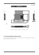
Installing BDU 280 (11.02) 315 (12.40) 303 (11.93) 42 (1.65) 44.1 (1.74) 485.7 (19.12) 0.5 (0.0) 191.5 (7.54) Unit: mm (inch) Figure 17: BDU Dimensions (19-inch Rack Mounting Type_Optional) 6.2 Selecting BDU Installation Site The BDU should be installed below the deck in a location that is dry, cool, and ventilated. The front panel of BDU should be easily accessible to users.
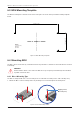
FB250 - Marine Satellite Communication System 6.3 BDU Mounting Template The BDU mounting holes must be in the exact same place as shown in the provided mounting template below. 126.8 mm (4.99") 300 mm (11.81") Drill Hole Ф 3.8 mm (0.14") diameter in 4 positions Figure 18: BDU Mounting Template 6.4 Mounting BDU The BDU can be mounted in any orientation but for best performance, Intellian recommends that it is mounted horizontally.
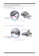
Installing BDU 6.4.2 19-inch Rack Mounting Type (Optional) Intellian offers the BDU Rack Mount Kit (separate purchase) including the rackmount plate and connector tray to mount the BDU in a 19" rack. 1. Using the Screws supplied, attach the connector tray to the BDU. Flat Head Screw, M3 x 6L (3 ea) Connector Tray Figure 20: Attach Connector Tray to BDU 2. Using the Screws supplied, attach the rackmount plate to the BDU.
FB250 - Marine Satellite Communication System 3. Slide the BDU assembly into a 19" rack frame. Mount the screws in each side through the holes in the front and fasten the screws to the rack. Make sure that the BDU assembly is mounted securely according to the requirements for your 19" rack. In case of using a provided AC-DC adapter for AC power connection, mount it securely in a safe place. After connecting all cables, fix the cables on the end of the connector tray using cable ties.
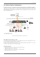
Installing BDU 6.6 Antenna System Configuration The basic system consists of one antenna and one BDU. Separate purchase of standard items including POTS phones, SIP phones, computers, etc. may be needed. A modem can be connected to the WAN port for data at least-cost routing operations. Voice calls are always routed through the Iridium system unless using a data call application. For your satellite communication system to work properly, connect the cables according to the configuration below.
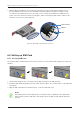
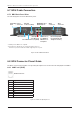
FB250 - Marine Satellite Communication System 6.7 BDU Cable Connection 6.7.1 BDU Back Panel View The following figure shows the BDU back panel. Grounding Power Stud Connector Antenna Connector (TNC) WAN (Wide Area Network) Port Wi-Fi Connector SIM Card Slot **PoE (Power *LAN Port 1, 2, over Ethernet) 3, 4 (RJ45) for Reset Button Port 1, 2 (RJ45) SIP Phones or Computers GPIO Connector Phone Port (RJ14) for POTS (Plain Old Telephone Service) * All LAN ports are IEEE 802.3 compliant.
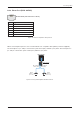
Installing BDU 6.8.2 Phone Port (RJ14 & 6P4C) RJ14 & 6P4C (6-Positions 4-Contacts) Pin Signal 1 N/A 2 T2+ (POTS Phone 2, no. 102) 3 R1- (POTS Phone 1, no. 101) 4 T1+ (POTS Phone 1, no. 101) 5 R2- (POTS Phone 2, no. 102) 6 N/A Figure 26: Phone Port (RJ14 & 6P4C) Pinout When connecting RJ14 phones, it is recommended to use a separate cable splitter (customer supplied). The POTS phone 1 (no. 101) is connected to a pair of Pin 3 (R1-) and Pin 4 (T1+) wires. The POTS phone 2 (no.
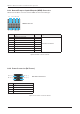
FB250 - Marine Satellite Communication System 6.8.3 General Purpose Inputs/Outputs (GPIO) Connector All wires for the GPIO connector must use AWG 24 unscreened wire type. 2 4 6 8 10 12 14 16 GPIO Connector 1 3 5 7 9 11 13 15 Pin Signal Pin 1 External Power Input 2 3 Input 1 4 5 Input 2 6 7 Reserved 8 9 Output 1 10 11 Output 2 12 12 Output 3 14 15 Remote Power On/Off 16 Signal External Power Return Figure 28: GPIO Connector Pinout 6.8.
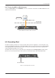
Installing BDU 6.8.5 Connecting BDU to ADU (Antenna) Connect the RF Cable from the ANTENNA connector on the back of the BDU to the RF Connector on the radome bottom (Antenna). ADU (Antenna) TX, RX, 48V DC Power Above Decks Below Decks Antenna BDU Figure 30: BDU to Antenna Cable Connection 6.9 Grounding Stud The BDU should be grounded. Use a heavy ground cable (customer supplied) to connect the BDU to the vessel’s ground during normal use.
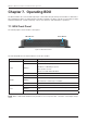
FB250 - Marine Satellite Communication System Chapter 7. Operating BDU The BDU and ADU are connected through single coaxial cable through which power from BDU is delivered to ADU and Ethernet data is exchanged between the BDU and ADU. The BDU controller is responsible for all the terminal management, system monitoring, control, error detection, and maintenance operations. 7.1 BDU Front Panel The following figure shows the BDU's front panel.
Operating BDU 7.2 Powering On System Use the power ON/OFF button on the BDU’s front panel. Wait for all LED indicators to turn green to indicate the system is completely powered up. 7.3 Making POTS Phone Call To make POTS phone calls, do as follows: 1. Connect an ethernet cable from the Phone Port (RJ14) on the back of the BDU to the POTS phone. NOTE NOTE When connecting a cable to Phone Port (RJ14), refer to the following; The analog phone 1 (no.
FB250 - Marine Satellite Communication System 7.4 Using PoE Devices 7.4.1 Accessing Internet To use PoE Devices and Wireless Devices, you need to access the Internet. The network is automatically configured by DHCP without the need for additional PC IP configuration. 1. Connect an Ethernet cable from the PoE Port 1 or PoE Port 2 on the back of the BDU to devices. The network connection is established automatically. 2. Use the following IP address to access the Intellian AptusLX Web page. • IP Address: 192.
Operating BDU 7.5.3 Setting up Wi-Fi You can connect to the BDU via Wi-Fi for easy management and control whenever you are on the vessel. 1. Bring the Wi-Fi Antenna located in the BDU package. Plug the Wi-Fi Antenna into the USB port on the back of the BDU. 2. Connect an Ethernet cable from the LAN Port 1, LAN Port 2, LAN Port 3, or LAN Port 4 on the back of the BDU to the LAN port of PC. The network connection is established automatically. 3.
FB250 - Marine Satellite Communication System 3. The registration window will appear in the pop-up window. Enter the new extension information. When you want to use the external call, select the Inbound Line and Outbound Line. Click the Update button. 1 202 3 4. Check the new extension added. 7.5.4 Making Wireless Device Call Using Grandstream Wave App (Recommended) through Mobile Phone To make a call on your mobile phone, Intellian recommends using the Grandstream Wave app.
Using AptusLX Chapter 8. Using AptusLX 8.1 Introduction With the embedded AptusLX software, the antenna can be monitored, controlled, and diagnosed remotely, anytime through the TCP/IP protocol. It saves your time and cost generated by various maintenance activities such as operating firmware upgrades, tracking parameter resets, and system diagnosis, etc. 8.1.1 How to Access Internal Webpage of BDU The network is automatically configured by DHCP with no additional PC IP configuration. 1.
FB250 - Marine Satellite Communication System 8.2 Main Page 8.2.1 Page Login The Intellian software Aptus provides different user access levels to protect the system for safe operation. Depending on the user level, the accessible range of functions in the software can be limited. 1. Log into the BDU by typing in User Name and Password information.
Using AptusLX 8.3 Top Menus Once you log in, the following information and menus are displayed. The overall state of the system is always displayed in the system status field. 1 2 3 8 No. 1 2 3 4 4 5 6 9 10 Item Description Satellite Status Displays the status of the satellite network connection. • Off: The system is not detected in the satellite network. • Steady Green: The system is detected in the satellite network. Ready to connect.
FB250 - Marine Satellite Communication System 8.4 Account Menu Click the Intellian button to manage the user account. The User and Info menus are for user management. Click the Logout button to log- out of the AptusLX web page. 1 2 8.4.1 User 1 2 3 4 5 No. Item Description 1 User Updates your password and ID. 2 User ID Change You can change your password. • ID: Displays the user current ID. • New ID: Enter the new ID you want to change. Click the Apply button to set the ID to the new ID.
Using AptusLX 8.5 Dashboard The Dashboard menu is displayed as below to provide quick monitoring of the antenna status. The Dashboard helps you arrange panels on a single screen while providing you with a broad view of a variety of information at once. NOTE NOTE NOTE To send SMS click the letter icon. Then the pop-up window is opened. Write a message (Standard 3G, up to 160 characters per SMS). Click the Send button.
FB250 - Marine Satellite Communication System 8.6 Status This menu displays the Network, Wi-Fi, Phone/PBX, Data, SIM, Terminal Info, and External GPIO function. 8.6.1 Network 1 2 3 4 5 No. Item Description Network Displays the information about a network and ports. 2 Network Status Displays the network information in use. • LAN IP: displays the network IP address (Factory default: 192.168.0.1). • Subnet Mask: displays the subnet mask (Factory default: 255.255.255.0).
Using AptusLX 8.6.2 Wi-Fi 1 2 3 No. Item Description 1 Wi-Fi Displays Wi-Fi access information. Displays the Wi-Fi access point configuration. 2 Wi-Fi Status 3 Mac Filter List • • • • • • Status: displays the Wi-Fi status (Active / Inactive). SSID: displays the SSID network name. Mac Filler: displays the MAC address filtering status (Enable/Disable). SSID Broadcast: displays the SSID broadcast status (Enable/Disable). Channel: displays the WLAN (wireless local area network) channel in use.
FB250 - Marine Satellite Communication System 8.6.3 Phone/PBX 1 2 3 No. 1 Item Description Phone/PBX Displays the phone and Private Automatic Branch Exchange (PABX) status. Displays the extension number and details. 2 Extension Management 3 Call History • Extension: displays the registered extension. • Inbound Line: displays the inbound line in use through the blue indicator. • Outbound Line: displays the outbound line. Displays the made and received call history log.
Using AptusLX 8.6.4 Data 2 1 3 4 5 No. Item Description 1 Data Displays the data setting status. 2 Routing Displays the data route (None, Satellite Only, WAN Only) in use. 3 Port Forwarding Displays the port forwarding data information. 4 Protocol Forwarding Displays the protocol forwarding data information. 5 Displays the connected/disconnected data call history log. You can set view Data Call History details from the drop-down list.
FB250 - Marine Satellite Communication System 8.6.5 SIM 2 1 No. Item Description 1 SIM Displays information about the SIM card. Configuration Displays the SIM card information in use. • Connected: displays connection status of the SIM card. The SIM must be inserted. • IMSI: displays a unique identifier to the SIM card.
Using AptusLX 8.6.6 Terminal info 2 1 3 4 No. Item Description 1 Terminal info Displays the system terminal information. 2 BDU Displays BDU information in use. 3 ADU Displays ADU information in use. 4 Core Module Displays the core module information in use.
FB250 - Marine Satellite Communication System 8.6.7 External GPIO 2 1 No. 3 Item Description 1 External GPIO Displays external GPIO. 2 Inputs Displays input information in use. 3 Outputs Displays output information in use.
Using AptusLX 8.7 Settings This menu sets and displays the Network, Wi-Fi, Firewall, Phone/PBX, Data, Satellite, SMS, Service Profile, Service User Group, Device Classification, Traffic Flow Template, SIM, External GPIO, Restricted Dialing, Multi Voice, NSD, and MST function. 8.7.1 Network 1 2 3 No. 1 2 Item Description Network Sets the information about a network and ports. Network Config Sets the network configuration.
FB250 - Marine Satellite Communication System 8.7.2 Wi-Fi 1 2 3 4 No. Item Description 1 Wi-Fi Sets the Wi-Fi access information. Sets the Wi-Fi access point configuration. 2 Wi-Fi Config • Activate: sets the Wi-Fi function by toggling the activation button (Enable/ Disable). • SSID: the SSID is the network name shared among all devices in a wireless network. The SSID must be identical for all devices in the wireless network.
Using AptusLX 8.7.3 Firewall 2 1 3 No. 1 Item Description Firewall Sets the firewall, network security system, which monitors and controls incoming and outgoing network traffic based on predetermined security rules. Sets the firewall configuration. 2 Firewall Config • Activate: sets the firewall function by toggling the activation button (Enable/ Disable). • Inbound Default Action: select the default settings for the incoming network from the drop-down list (Accept/Drop).
FB250 - Marine Satellite Communication System 8.7.4 Phone/PBX 2 1 No. 1 Item Description Phone/PBX Sets the phone and Private Automatic Branch Exchange (PABX). Sets the extension number and details. • Edit button: to edit the registered extension, click the edit button. Then the pop-up window is opened. You can edit details. • Delete button: to delete the registered extension, click the delete button. (Extension 101 and 102 have no delete button.