F4-A250-S Marine FleetBroadband Installation & Operation User Guide
Serial number of the product This serial number will be required for all troubleshooting or service inquiries. © 2020 Intellian Technologies, Inc. All rights reserved. Intellian and the Intellian logo are trademarks of Intellian Technologies, Inc., registered in the U.S. and other countries. The F4-A250-S is a trademark of Intellian Technologies, Inc. Intellian may have patents, patent applications, trademarks, copyrights, or other intellectual property rights covering subject matter in this document.
Table of Contents Table of Contents Chapter 1. Precautions 9 1.1 Warnings, Cautions, and Notes 9 1.2 General Precautions 9 Chapter 2. Certifications 11 2.1 Certifications 11 Chapter 3. Introduction 12 3.1 Introduction of F4-A250-S 12 3.2 Features of F4-A250-S 12 3.3 Overview of FleetBroadband 13 3.3.1 BGAN Services 13 3.3.2 FleetBroadband Service Coverage 13 Chapter 4. Planning Installation 14 4.1 Selecting Installation Site 14 4.1.1 Avoiding RF Interference 14 4.1.
FB250 - Marine Satellite Communication System Chapter 6. Installing BDU 30 6.1 BDU Dimensions 30 6.2 Selecting BDU Installation Site 31 6.3 BDU Mounting Template 32 6.4 Mounting BDU 32 6.4.1 Direct Mounting Type 32 6.4.2 19-inch Rack Mounting Type (Optional) 33 6.5 Setting up SIM Card 34 6.5.1 Inserting SIM Card 34 6.6 Antenna System Configuration 35 6.6.1 Data sessions and voice calls 6.7 BDU Cable Connection 35 36 6.7.1 BDU Back Panel View 36 6.8 BDU Connector Pinout Guide 36 6.
Table of Contents 8.4 Account Menu 48 8.4.1 User 48 8.5 Dashboard 49 8.6 Status 50 8.6.1 Network 50 8.6.2 Wi-Fi 51 8.6.3 Phone/PBX 52 8.6.4 Data 53 8.6.5 SIM 54 8.6.6 Terminal info 55 8.6.7 External GPIO 56 8.7 Settings 57 8.7.1 Network 57 8.7.2 Wi-Fi 58 8.7.3 Firewall 59 8.7.4 Phone/PBX 60 8.7.5 Data 61 8.7.6 Satellite 62 8.7.7 SMS 63 8.7.8 Service Profile 64 8.7.9 Service User Group 66 8.7.10 Device Classification 67 8.7.11 Traffic Flow Template (TFT) 68 8.7.
FB250 - Marine Satellite Communication System 9.2 Environmental Specification 86 Chapter 10. Warranty 87 10.1 Warranty Policy 87 Chapter 11. Appendix 88 11.1 Appendix A.
Table of Contents List of Figures Chapter 4. Planning Installation 14 Figure 1: Potential RF Interference 14 Figure 2: RF Hazard Precautions 15 Figure 3: Above Deck Unit (ADU) / Antenna Unit 16 Figure 4: Below Deck Unit (BDU) 16 Figure 5: Unpacking System Package (with ADU & BDU Sub-package) 22 Figure 6: Unpacking BDU Package 22 Figure 7: Unpacking ADU Package 23 Chapter 5.
FB250 - Marine Satellite Communication System Chapter 7.
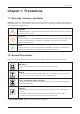
Precautions Chapter 1. Precautions 1.1 Warnings, Cautions, and Notes WARNING, CAUTION, and NOTE statements are used throughout this manual to emphasize important and critical information. You must read these statements to help ensure safety and to prevent product damage. The statements are defined below. WARNING WARNING WARNING indicates a potentially hazardous situation which, if not avoided, could result in death or serious injury.
FB250 - Marine Satellite Communication System * Shock Hazard: To minimize shock hazard and to protect against lightning, you must connect the equipment chassis and cabinet to an electrical ground. Make sure the system is correctly grounded and power is off when installing, configuring, and connecting components. * Do not operate in an explosive atmosphere: Do not operate the equipment in explosive environments or in the presence of flammable gases.
Certifications Chapter 2. Certifications 2.1 Certifications This device complies with part 15 of the FCC Rules and with Industry Canada licence-exempt RSS standard(s). Operation is subject to the following two conditions: (1) This device may not cause harmful interference, and (2) this device must accept any interference received, including interference that may cause undesired operation.
FB250 - Marine Satellite Communication System Chapter 3. Introduction 3.1 Introduction of F4-A250-S Intellian’s FleetBroadband 250 maritime voice and data communication terminal connects to Inmarsat’s global GEO L-band network, providing highly reliable, safe, and guaranteed service. Intellian’s F4-A250-S provides up to 284 kbps IP data and 128 kbps streaming IP with VoIP service and SMS, compatible with the GSM network standard.
Introduction 3.3 Overview of FleetBroadband 3.3.1 BGAN Services The Broadband Global Area Network (BGAN) is a global Satellite Internet Network using portable terminals. The terminals are usually connected to a laptop computer to access broadband Internet in remote locations, where a line-of-sight to the satellite exists. The user can make phone calls, access the Internet, check e-mail, download files, or perform any other Internet activity using the terminals.
FB250 - Marine Satellite Communication System Chapter 4. Planning Installation The antenna installation requires precaution and safety measures. Failure to follow the correct installation process may lead to injury of the installer and/or cause damage to the system. In order to maximize the performance of the system, a thorough review of this installation guide is strongly recommended, as well as executing the installation process as it is noted in this manual. 4.
Planning Installation 4.1.2 RF Hazard Precautions The antenna is designed to be used with radiation transmitting equipment manufactured by others. Exposure to RF radiation, including exposure associated with improper use of the transmitting equipment, may be hazardous to people who work close to the Above Deck Unit. Ensure the safety of personnel who work with in the system. During transmission, ensure to keep the minimum safety distance.
FB250 - Marine Satellite Communication System 4.2 System Package 4.2.1 Above Deck Unit (ADU) / Antenna Unit The Above Deck Unit (ADU) of F4-A250-S consists of a medium-size maritime 2-axis stabilized BGAN antenna, active RF switch, BRM, and GNSS circuit. The antenna unit is protected from a severe marine environment by a radome. The ADU and BDU are connected by a single coaxial cable which delivers RF signals and DC power. Figure 3: Above Deck Unit (ADU) / Antenna Unit 4.2.
Planning Installation 4.2.3 Packing List Before beginning installation, make sure you have all the included components. The ADU Package & BDU Package are provided in one box. NOTE: The SIM card is provided by the service provider and may be packaged separately.
FB250 - Marine Satellite Communication System Antenna Pole Mount Kit (Optional) The Antenna Pole Mount Kit can be purchased separately. When this kit is supplied, it is provided in a separate box.
Planning Installation 4.3.2 DC Power Cable You can supply DC power to the BDU in the following methods depending on the power supply available in the vessel. Intellian provides a DC Power Cable, an AC-DC Adapter (optional), and a Terminal Block for the power connections. 1. Connecting to Battery (default): Using the DC power cable (1 m), supply the DC power to the BDU from the battery. The power cable is installed with the Molex connector (P/No. 1716920204, Max. AWG 12). Use 1~2 m (3.28~6.
FB250 - Marine Satellite Communication System Terminal Blocks Dimension Rating/ Pole F(mm) G(mm) Hole(Ø) L(mm) W(mm) H(mm) Weight 60A 3P 28 16 5.2 85 40 36 142g Wiring Lug Dimension E 14.5mm F Min. Ø6.1 W Max. 16.8mm L 35.
Planning Installation Black (negative) For the DC power wires, Red (positive) and Black (negative), you can connect each wire with other wires using the terminal block. Red (positive) 1. Open the top cover of the terminal block. 2. Unscrew the 1st position terminal using a Phillips screwdriver. Insert the ring connector of the Red (positive) wire to the terminal and tighten the screw back into the terminal. 3. Unscrew the 3rd position terminal using a Phillips screwdriver.
FB250 - Marine Satellite Communication System 4.4 Unpacking System Package 115 (4.52) Follow steps for easy and safe unpacking. The system package consists of two sub-packages that an ADU Package and a BDU Package. 52 0( 20 ) .47 .47 ) 20 0( BDU Package 50 5( ) .88 19 5( 19 .88 ) 50 360 (14.17) 505 (19.88) Unit: mm (inch) 52 ADU Package 50 5( 19 .88 ) 5 ) .88 19 ( 05 Figure 5: Unpacking System Package (with ADU & BDU Sub-package) 1.
Planning Installation 2. Take out the ADU package including an Antenna Mounting Template, an ADU Bolt Kit, an RF Cable, and an ADU Unit.
FB250 - Marine Satellite Communication System Chapter 5. Installing ADU 5.1 Antenna Dimensions Confirm the height and diameter of the antenna unit shown in the following figure before installing it. 294 (11.57) Unit: mm (inch) BOW Ø250 (9.84) Ø291 (11.
Installing ADU 5.2 ADU Mounting Hole Pattern Use the supplied mounting template when drilling mounting holes on the mast. The hole placement for the antenna must match the mounting hole pattern on the template. The lower radome has an industry-standard mounting hole with four mounting points. This hole pattern is compatible with other companies' mounting holes. Use the mounting holes to secure the antenna to the desired mounting surface.
FB250 - Marine Satellite Communication System 5.3 Mast Designing (Installation Example) The installation mast must be robust enough to prevent flection, vibration, and sway when an external force is exerted on the mast with antenna and radome. Intellian strongly recommends installing the antenna less than 1200mm (47") above the deck. The flange thickness must be at least 8 mm. Refer to the following mast drawing for more details. Mounting Plate Ø220 (8.66) Unit: mm (inch) Bolt Hole Ø175.4 (6.9) 8 (0.
Installing ADU 5.4 Mounting Antenna The lower radome has an industry-standard mounting hole with four mounting points. This hole pattern is compatible with other companies' mounting holes. Use the mounting holes to secure the antenna to the desired mounting surface. Bring the provided Antenna Mounting Template and the ADU Bolt Kit from the ADU package. Create the appropriate hole pattern in the desired mounting surface. 5.4.
FB250 - Marine Satellite Communication System 2. A The position between end of legs of the pole bracket must be aligned with the BOW direction. Place the pole bracket onto the pole tube then tighten them using bolts. Before assembling bolts, apply Loctite #263 to the bolt's threads to ensure the bolts are fastened firmly. x Four Times M6 x 20L Hex. Bolt M6 Spring Washer BOW Use a torque wrench. M6 Flat Washer A Pole Bracket Pole Tube Figure 14: Installing Pole Bracket 3.
Installing ADU 5.5 Connecting RF Cable to Antenna The cable must be routed from the antenna and through various areas of the ship to end up at the Below Deck Unit. When pulling the cables in place, avoid sharp bends, kinking, and excessive force. After placement, seal the deck penetration gland and tie the cable securely in place. The cable bracket must be installed on the mast to fix the relevant cable. The gooseneck must be installed on the side of the mast to protect the relevant cable against water.
FB250 - Marine Satellite Communication System Chapter 6. Installing BDU The Intellian offers two versions of BDU installation, one can be installed to the surface of the wall or desktop, and one can be installed to the 19-inch rack frame using the BDU Rack Mount Kit (separate purchase). 6.1 BDU Dimensions Confirm the dimension of the BDU before installing it. 42.1 (1.65) 280 (11.02) 315 (12.40) 2 (1.65) 190 (7.48) 210 (8.