
User's Guide


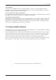
Table Of Contents
- Chapter 1. Precautions
- Chapter 2. Certifications
- Chapter 3. Introduction
- Chapter 4. Planning Installation
- Chapter 5. Installing ADU
- Chapter 6. Installing BDU
- Chapter 7. Operating BDU
- Chapter 8. Using AptusLX
- Chapter 9. Specification
- Chapter 10. Warranty
- Chapter 11. Appendix
- Chapter 1. Precautions
- Chapter 4. Planning Installation
- Chapter 5. Installing ADU
- Figure 9: Antenna Dimensions
- Figure 10: ADU Mounting Template
- Figure 11: Recommended Mast Design using Inner Holes (with M6 Bolts)
- Figure 12: Recommended Mast Design using Outer Holes (with M10 Bolts)
- Figure 13: Mounting Antenna using Inner Holes (with M6 Bolts)
- Figure 14: Mounting Antenna using Outer Holes (with M10 Bolts)
- Figure 15: Installing 40A Pole Bushing inside Pole Tube
- Figure 16: Installing Pole Bracket
- Figure 17: Mounting Antenna on Pole Mounted Bracket
- Figure 18: Vent Hole
- Figure 19: Connecting RF Cable using Inner Holes (with M6 Bolts)
- Figure 20: Connecting RF Cable using Outer Holes (with M10 Bolts)
- Chapter 6. Installing BDU
- Figure 21: BDU Dimensions (Direct Mounting Type)
- Figure 22: BDU Dimensions (19-inch Rack Mounting Type_Optional)
- Figure 23: BDU Mounting Template
- Figure 24: Direct Mounting of BDU
- Figure 25: Attach Connector Tray to BDU
- Figure 26: Attach Rackmount Plate to BDU
- Figure 27: Intellian C700 System with Connected Devices
- Figure 28: BDU Back Panel View
- Figure 29: LAN Ports (RJ45) Pinout
- Figure 30: Phone Port (RJ14 & 6P4C) Pinout
- Figure 31: Using Cable Splitter with RJ14 Phones
- Figure 32: GPIO Connector Pinout
- Figure 33: Power Connector Pinout
- Figure 34: BDU to Antenna Cable Connection
- Figure 35: Grounding Stud Connection
- Chapter 7. Operating BDU

9
Precautions
* Shock Hazard:
To minimize shock hazard and to protect against lightning, you must connect the equipment chassis
and cabinet to an electrical ground. Make sure the system is correctly grounded and power is off when
installing, conguring, and connecting components.
* Do not operate in an explosive atmosphere:
Do not operate the equipment in explosive environments or in the presence of ammable gases. Operating
this equipment in such an environment causes a denite safety hazard.
* Keep away from living circuits:
Operating personnel must at all times observe all safety regulations. Do not replace components or make
adjustment inside the equipment with any power supply turned on. Under certain conditions, dangerous
potentials may exist in the power supplies even with the power cable removed. To avoid injuries, always
remove the power and discharge a circuit before touching it.
Figure 1: Earth Showing Iridium Satellite in Six Dened Orbital Planes
1.3 Iridium Satellite Network
The Iridium satellite network is comprised of 66 low-earth orbiting (LEO), cross-linked satellites, providing
voice and data coverage over Earth’s entire surface.
At only 476 (780 km) from the earth, the proximity of Iridium’s LEO network means pole-to-pole coverage,
a shorter transmission path, stronger signals, lower latency, and shorter registration time than with GEO
satellites. The network is considered a meshed constellation of interconnected, cross-linked satellites so
that each satellite “talks” with the other nearby satellites in front, behind, and adjacent orbits.
In space, each Iridium satellite is linked to up to four others creating a dynamic network that routes trafc
among satellites to ensure global coverage, even when traditional local systems are unavailable.