
User's Guide
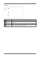
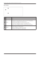
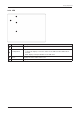
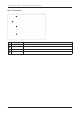
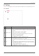
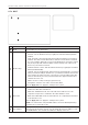
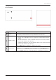
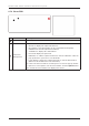
Table Of Contents
- Chapter 1. Precautions
- Chapter 2. Certifications
- Chapter 3. Introduction
- Chapter 4. Planning Installation
- Chapter 5. Installing ADU
- Chapter 6. Installing BDU
- Chapter 7. Operating BDU
- Chapter 8. Using AptusLX
- Chapter 9. Specification
- Chapter 10. Warranty
- Chapter 11. Appendix
- Chapter 1. Precautions
- Chapter 4. Planning Installation
- Chapter 5. Installing ADU
- Figure 9: Antenna Dimensions
- Figure 10: ADU Mounting Template
- Figure 11: Recommended Mast Design using Inner Holes (with M6 Bolts)
- Figure 12: Recommended Mast Design using Outer Holes (with M10 Bolts)
- Figure 13: Mounting Antenna using Inner Holes (with M6 Bolts)
- Figure 14: Mounting Antenna using Outer Holes (with M10 Bolts)
- Figure 15: Installing 40A Pole Bushing inside Pole Tube
- Figure 16: Installing Pole Bracket
- Figure 17: Mounting Antenna on Pole Mounted Bracket
- Figure 18: Vent Hole
- Figure 19: Connecting RF Cable using Inner Holes (with M6 Bolts)
- Figure 20: Connecting RF Cable using Outer Holes (with M10 Bolts)
- Chapter 6. Installing BDU
- Figure 21: BDU Dimensions (Direct Mounting Type)
- Figure 22: BDU Dimensions (19-inch Rack Mounting Type_Optional)
- Figure 23: BDU Mounting Template
- Figure 24: Direct Mounting of BDU
- Figure 25: Attach Connector Tray to BDU
- Figure 26: Attach Rackmount Plate to BDU
- Figure 27: Intellian C700 System with Connected Devices
- Figure 28: BDU Back Panel View
- Figure 29: LAN Ports (RJ45) Pinout
- Figure 30: Phone Port (RJ14 & 6P4C) Pinout
- Figure 31: Using Cable Splitter with RJ14 Phones
- Figure 32: GPIO Connector Pinout
- Figure 33: Power Connector Pinout
- Figure 34: BDU to Antenna Cable Connection
- Figure 35: Grounding Stud Connection
- Chapter 7. Operating BDU

57
Using AptusLX
No. Item Description
1
Network
Sets
the information about a network and ports.
2
Network Cong
Sets the network conguration.
• DHCP: sets the DHCP function by toggling the activation button (Activate/
Inactivate).
• Start IP: sets the start range of lease IP address.
• End IP: sets the end range of lease IP address.
• Subnet Mask: sets the subnet mask (Factory default: 255.255.255.0).
• Gateway: sets the gateway IP address.
• Lease Time: sets the lease time (sec).
Click the Apply button to apply the settings to the system.
3
Port
Sets
each switch port.
• Name: displays the port mane (port 1, 2, 3, and 4).
• PoE Status: sets the PoE function by toggling the activation button on port 1
and 2.
• Port Type: the port 1 is xed for LAN. The port 4 can be selected as LAN,
SDF, or WAN from the drop-down list. Port 2 and 3 can be selected as LAN
or SDF from the drop-down list.
• Link Status: displays the link status (Up/Down).
Click the Apply button to apply the settings to the system.
3
1
2
8.7 Settings
This menu sets and displays the Network, Wi-Fi, Firewall, Phone/PBX, Data, SDF, and External GPIO function.
8.7.1 Network