
User's Guide
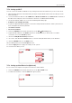
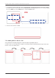
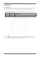
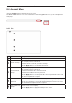
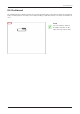
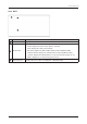
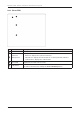
Table Of Contents
- Chapter 1. Precautions
- Chapter 2. Certifications
- Chapter 3. Introduction
- Chapter 4. Planning Installation
- Chapter 5. Installing ADU
- Chapter 6. Installing BDU
- Chapter 7. Operating BDU
- Chapter 8. Using AptusLX
- Chapter 9. Specification
- Chapter 10. Warranty
- Chapter 11. Appendix
- Chapter 1. Precautions
- Chapter 4. Planning Installation
- Chapter 5. Installing ADU
- Figure 9: Antenna Dimensions
- Figure 10: ADU Mounting Template
- Figure 11: Recommended Mast Design using Inner Holes (with M6 Bolts)
- Figure 12: Recommended Mast Design using Outer Holes (with M10 Bolts)
- Figure 13: Mounting Antenna using Inner Holes (with M6 Bolts)
- Figure 14: Mounting Antenna using Outer Holes (with M10 Bolts)
- Figure 15: Installing 40A Pole Bushing inside Pole Tube
- Figure 16: Installing Pole Bracket
- Figure 17: Mounting Antenna on Pole Mounted Bracket
- Figure 18: Vent Hole
- Figure 19: Connecting RF Cable using Inner Holes (with M6 Bolts)
- Figure 20: Connecting RF Cable using Outer Holes (with M10 Bolts)
- Chapter 6. Installing BDU
- Figure 21: BDU Dimensions (Direct Mounting Type)
- Figure 22: BDU Dimensions (19-inch Rack Mounting Type_Optional)
- Figure 23: BDU Mounting Template
- Figure 24: Direct Mounting of BDU
- Figure 25: Attach Connector Tray to BDU
- Figure 26: Attach Rackmount Plate to BDU
- Figure 27: Intellian C700 System with Connected Devices
- Figure 28: BDU Back Panel View
- Figure 29: LAN Ports (RJ45) Pinout
- Figure 30: Phone Port (RJ14 & 6P4C) Pinout
- Figure 31: Using Cable Splitter with RJ14 Phones
- Figure 32: GPIO Connector Pinout
- Figure 33: Power Connector Pinout
- Figure 34: BDU to Antenna Cable Connection
- Figure 35: Grounding Stud Connection
- Chapter 7. Operating BDU

45
Using AptusLX
8.3 Top Menus
Once you log in, the following information and menus are displayed. The overall state of the system is
always displayed in the system status eld.
No. Item Description
1
Satellite Status
Displays the status of the satellite network connection.
• Off: The system is not detected in the satellite network.
• Steady Green: The system is detected in the satellite network. Ready to
connect.
• Blinking Green (Acquiring): The system is connecting to the satellite network.
• Steady Blue: The system is registered and connected to the satellite network.
• Steady Red: Registration on the network was denied. If the SIM card is
inserted incorrectly, insert the SIM card in place. Refer to the "6.5.1 Inserting
SIM Card" on page 31. If there is no error with the SIM card status, contact
the service provider.
2
WAN Status
Displays the status of the wide-area network (WAN) connection. The system
connects to the WAN according to the setting of the routing policy. You can also
check the status of the WAN connection on the 'Current Route Selection' panel
of the "8.5 Dashboard" on page 47.
• Steady Blue: The WAN is connected.
• Red/Off: The WAN is not connected.
3
Wi-Fi Status
Displays the status of the Wi-Fi connection.
• Off: The Wi-Fi connection is disabled.
• Steady Green: The Wi-Fi connection is enabled. Ready to connect.
• Steady Blue: The Wi-Fi is connected.
4
Signal Strength
Displays the current signal level.
• Off: The network is disabled.
• Steady Green: The network is enabled. Displays the current signal level.
5
System Power
Displays the current system power.
• Steady Blue: The system is in normal operation.
• Steady Red: A error is detected.
6
Call
Displays the status of the call connection.
• Steady Green: The extension call is available.
• Steady Blue: The extension and external call is available.
• Blinking Blue: The external call is active.
7
Main Menu
Select the Main Menu. Each main menu offers side menus on the left of the
screen.
8
Account Button
Select the
Intellian
button to manage your account details and select the
Logout menu to log out of the AptusLX web page.
1 2 3 5
6
7
8
4