
User's Guide
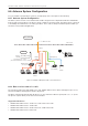

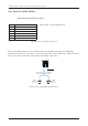

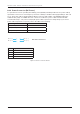
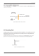

Table Of Contents
- Chapter 1. Precautions
- Chapter 2. Certifications
- Chapter 3. Introduction
- Chapter 4. Planning Installation
- Chapter 5. Installing ADU
- Chapter 6. Installing BDU
- Chapter 7. Operating BDU
- Chapter 8. Using AptusLX
- Chapter 9. Specification
- Chapter 10. Warranty
- Chapter 11. Appendix
- Chapter 1. Precautions
- Chapter 4. Planning Installation
- Chapter 5. Installing ADU
- Figure 9: Antenna Dimensions
- Figure 10: ADU Mounting Template
- Figure 11: Recommended Mast Design using Inner Holes (with M6 Bolts)
- Figure 12: Recommended Mast Design using Outer Holes (with M10 Bolts)
- Figure 13: Mounting Antenna using Inner Holes (with M6 Bolts)
- Figure 14: Mounting Antenna using Outer Holes (with M10 Bolts)
- Figure 15: Installing 40A Pole Bushing inside Pole Tube
- Figure 16: Installing Pole Bracket
- Figure 17: Mounting Antenna on Pole Mounted Bracket
- Figure 18: Vent Hole
- Figure 19: Connecting RF Cable using Inner Holes (with M6 Bolts)
- Figure 20: Connecting RF Cable using Outer Holes (with M10 Bolts)
- Chapter 6. Installing BDU
- Figure 21: BDU Dimensions (Direct Mounting Type)
- Figure 22: BDU Dimensions (19-inch Rack Mounting Type_Optional)
- Figure 23: BDU Mounting Template
- Figure 24: Direct Mounting of BDU
- Figure 25: Attach Connector Tray to BDU
- Figure 26: Attach Rackmount Plate to BDU
- Figure 27: Intellian C700 System with Connected Devices
- Figure 28: BDU Back Panel View
- Figure 29: LAN Ports (RJ45) Pinout
- Figure 30: Phone Port (RJ14 & 6P4C) Pinout
- Figure 31: Using Cable Splitter with RJ14 Phones
- Figure 32: GPIO Connector Pinout
- Figure 33: Power Connector Pinout
- Figure 34: BDU to Antenna Cable Connection
- Figure 35: Grounding Stud Connection
- Chapter 7. Operating BDU

36
Intellian C700 - Marine Satellite Communication System
Figure 33: Power Connector Pinout
6.8.4 Power Connector (DC Power)
DC Operation for vessels operating from battery power (default): Intellian provides the DC power cable (1
m) and wire connector for connecting DC power from a battery to the BDU directly (Input Range: 10.8~30
V DC). The power cable is supplied with the Molex connector (part number: 1716920204) and has the
maximum wire gauge of 12 AWG. The wire connector is used for DC power cable extension.Intellian
recommends using 1~2 m (3.28~6.56 ft) length power cable to prevent DC voltage drop. If you need a
power cable longer than 2 m (6.56 ft), refer to the table as the following.
Cable length Maximum Wire Size
5 m (16.40 ft) AWG 16
10 m (32.80 ft) AWG 14
20 m (65.61 ft) AWG 12
Pin 4 ( - )Pin 3 ( - )
Pin 2 ( + )Pin 1 ( + )
DC Power Connector
Pin Signal
1
+
2
+
3
-
4
-