
User's Guide
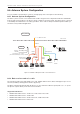

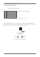

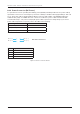
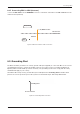
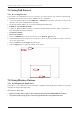
Table Of Contents
- Chapter 1. Precautions
- Chapter 2. Certifications
- Chapter 3. Introduction
- Chapter 4. Planning Installation
- Chapter 5. Installing ADU
- Chapter 6. Installing BDU
- Chapter 7. Operating BDU
- Chapter 8. Using AptusLX
- Chapter 9. Specification
- Chapter 10. Warranty
- Chapter 11. Appendix
- Chapter 1. Precautions
- Chapter 4. Planning Installation
- Chapter 5. Installing ADU
- Figure 9: Antenna Dimensions
- Figure 10: ADU Mounting Template
- Figure 11: Recommended Mast Design using Inner Holes (with M6 Bolts)
- Figure 12: Recommended Mast Design using Outer Holes (with M10 Bolts)
- Figure 13: Mounting Antenna using Inner Holes (with M6 Bolts)
- Figure 14: Mounting Antenna using Outer Holes (with M10 Bolts)
- Figure 15: Installing 40A Pole Bushing inside Pole Tube
- Figure 16: Installing Pole Bracket
- Figure 17: Mounting Antenna on Pole Mounted Bracket
- Figure 18: Vent Hole
- Figure 19: Connecting RF Cable using Inner Holes (with M6 Bolts)
- Figure 20: Connecting RF Cable using Outer Holes (with M10 Bolts)
- Chapter 6. Installing BDU
- Figure 21: BDU Dimensions (Direct Mounting Type)
- Figure 22: BDU Dimensions (19-inch Rack Mounting Type_Optional)
- Figure 23: BDU Mounting Template
- Figure 24: Direct Mounting of BDU
- Figure 25: Attach Connector Tray to BDU
- Figure 26: Attach Rackmount Plate to BDU
- Figure 27: Intellian C700 System with Connected Devices
- Figure 28: BDU Back Panel View
- Figure 29: LAN Ports (RJ45) Pinout
- Figure 30: Phone Port (RJ14 & 6P4C) Pinout
- Figure 31: Using Cable Splitter with RJ14 Phones
- Figure 32: GPIO Connector Pinout
- Figure 33: Power Connector Pinout
- Figure 34: BDU to Antenna Cable Connection
- Figure 35: Grounding Stud Connection
- Chapter 7. Operating BDU

33
Installing BDU
RJ45 Connector
Pin Signal
1 TD+
2 TD-
3 RD+
4 NC
5 NC
6 RD-
7 NC
8 NC
6.8 BDU Connector Pinout Guide
The BDU connector pins and their corresponding descriptions are shown in the following gures and tables
6.8.1 LAN Ports (RJ45)
* Cable Length: 1.5 meter (59.05 inches)
Figure 29: LAN Ports (RJ45) Pinout
6.7 BDU Cable Connection
6.7.1 BDU Back Panel View
The following gure shows the BDU back panel.
Figure 28: BDU Back Panel View
*LAN Port 1, 2,
3, 4 (RJ45) for
SIP Phones or
Computers
SIM Card Slot
Reset Button
Phone Port (RJ14)
for POTS (Plain Old
Telephone Service)
Antenna
Connector (TNC)
WAN (Wide Area
Network) Port
Power
Connector
Grounding
Stud
Wi-Fi
Connector
GPIO
Connector
**LAN Port 1, 2
(RJ45) for PoE
(Power over
Ethernet)
* All LAN ports are IEEE 802.3 compliant.
** Each PoE Port is designed to use 7.5W power. When using over
12.5W in one port, the PoE function will be stopped in port 1 or port 2.