
User's Guide
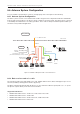

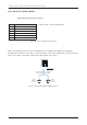

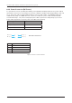
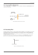

Table Of Contents
- Chapter 1. Precautions
- Chapter 2. Certifications
- Chapter 3. Introduction
- Chapter 4. Planning Installation
- Chapter 5. Installing ADU
- Chapter 6. Installing BDU
- Chapter 7. Operating BDU
- Chapter 8. Using AptusLX
- Chapter 9. Specification
- Chapter 10. Warranty
- Chapter 11. Appendix
- Chapter 1. Precautions
- Chapter 4. Planning Installation
- Chapter 5. Installing ADU
- Figure 9: Antenna Dimensions
- Figure 10: ADU Mounting Template
- Figure 11: Recommended Mast Design using Inner Holes (with M6 Bolts)
- Figure 12: Recommended Mast Design using Outer Holes (with M10 Bolts)
- Figure 13: Mounting Antenna using Inner Holes (with M6 Bolts)
- Figure 14: Mounting Antenna using Outer Holes (with M10 Bolts)
- Figure 15: Installing 40A Pole Bushing inside Pole Tube
- Figure 16: Installing Pole Bracket
- Figure 17: Mounting Antenna on Pole Mounted Bracket
- Figure 18: Vent Hole
- Figure 19: Connecting RF Cable using Inner Holes (with M6 Bolts)
- Figure 20: Connecting RF Cable using Outer Holes (with M10 Bolts)
- Chapter 6. Installing BDU
- Figure 21: BDU Dimensions (Direct Mounting Type)
- Figure 22: BDU Dimensions (19-inch Rack Mounting Type_Optional)
- Figure 23: BDU Mounting Template
- Figure 24: Direct Mounting of BDU
- Figure 25: Attach Connector Tray to BDU
- Figure 26: Attach Rackmount Plate to BDU
- Figure 27: Intellian C700 System with Connected Devices
- Figure 28: BDU Back Panel View
- Figure 29: LAN Ports (RJ45) Pinout
- Figure 30: Phone Port (RJ14 & 6P4C) Pinout
- Figure 31: Using Cable Splitter with RJ14 Phones
- Figure 32: GPIO Connector Pinout
- Figure 33: Power Connector Pinout
- Figure 34: BDU to Antenna Cable Connection
- Figure 35: Grounding Stud Connection
- Chapter 7. Operating BDU

32
Intellian C700 - Marine Satellite Communication System
6.6 Antenna System Conguration
For your satellite communication system to work properly, refer to the gure as the following.
6.6.1 Antenna System Conguration
The basic system consists of one antenna and one BDU. A typical user setup that includes the standard kit
items as well as a POTS phone, SIP phones, and a computer is shown in Figure. A modem can be connected
to the WAN port for data least-cost routing operations. Voice calls are always routed through the Iridium sys-
tem unless using a data call application.
6.6.2 Data sessions and voice calls
The System provides up to High quality voice calls, multiple data sessions, Wi-Fi, and supports up to 18 ex-
tensions (including 2 analog phones and 16 sip phones).
The BDU communicates directly with SIP phones on any of the three LAN user ports (LAN 1, 2, 3, or 4). The
SIP phones register directly to the SIP server in the BDU.
Supported VoIP Phones
• Grandstream GXP16 Series: 1610, 1615, 1620, 1625, 1628, 1630
• Grandstream GXP17 Series: 1760, 1780
• Grandstream GXP21 Series: 2120, 2130, 2135, 2140, 2160, 2170
• Grandstream GXV32 Series: 3240, 3275
Figure 27: Intellian C700 System with Connected Devices
Input Range: 10.8~30 V DC
(Recommended Voltage: 24 V DC)
Vessel’s
Ground
Switch Router
(Not supplied)
WAN
LAN 2
(RJ45)
LAN 1
(RJ45)
LAN 3
(RJ45)
LAN 4
(RJ45)
Phone (RJ14)
Above Decks
Below Decks
BDU
ADU (Antenna)
Antenna
TX, RX, 48V DC Power
Wireless Devices
SIP
Phone
POTS
Phone
PCPC
PC PC
LTE Modem
(Not supplied)
Grounding Stud