
User's Guide
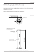
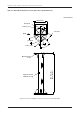
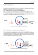
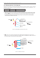

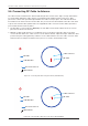
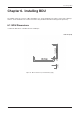
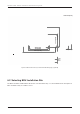
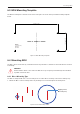
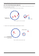
Table Of Contents
- Chapter 1. Precautions
- Chapter 2. Certifications
- Chapter 3. Introduction
- Chapter 4. Planning Installation
- Chapter 5. Installing ADU
- Chapter 6. Installing BDU
- Chapter 7. Operating BDU
- Chapter 8. Using AptusLX
- Chapter 9. Specification
- Chapter 10. Warranty
- Chapter 11. Appendix
- Chapter 1. Precautions
- Chapter 4. Planning Installation
- Chapter 5. Installing ADU
- Figure 9: Antenna Dimensions
- Figure 10: ADU Mounting Template
- Figure 11: Recommended Mast Design using Inner Holes (with M6 Bolts)
- Figure 12: Recommended Mast Design using Outer Holes (with M10 Bolts)
- Figure 13: Mounting Antenna using Inner Holes (with M6 Bolts)
- Figure 14: Mounting Antenna using Outer Holes (with M10 Bolts)
- Figure 15: Installing 40A Pole Bushing inside Pole Tube
- Figure 16: Installing Pole Bracket
- Figure 17: Mounting Antenna on Pole Mounted Bracket
- Figure 18: Vent Hole
- Figure 19: Connecting RF Cable using Inner Holes (with M6 Bolts)
- Figure 20: Connecting RF Cable using Outer Holes (with M10 Bolts)
- Chapter 6. Installing BDU
- Figure 21: BDU Dimensions (Direct Mounting Type)
- Figure 22: BDU Dimensions (19-inch Rack Mounting Type_Optional)
- Figure 23: BDU Mounting Template
- Figure 24: Direct Mounting of BDU
- Figure 25: Attach Connector Tray to BDU
- Figure 26: Attach Rackmount Plate to BDU
- Figure 27: Intellian C700 System with Connected Devices
- Figure 28: BDU Back Panel View
- Figure 29: LAN Ports (RJ45) Pinout
- Figure 30: Phone Port (RJ14 & 6P4C) Pinout
- Figure 31: Using Cable Splitter with RJ14 Phones
- Figure 32: GPIO Connector Pinout
- Figure 33: Power Connector Pinout
- Figure 34: BDU to Antenna Cable Connection
- Figure 35: Grounding Stud Connection
- Chapter 7. Operating BDU

26
Intellian C700 - Marine Satellite Communication System
5.6 Connecting RF Cable to Antenna
The cable must be routed from the antenna and through various areas of the ship to end up at the Below
Deck Unit. When pulling the cables in place, avoid sharp bends, kinking, and excessive force. After
placement, seal the deck penetration gland and tie the cable securely in place. The cable bracket must
be installed on the mast to x the relevant cable. The gooseneck must be installed on the side of the mast
to protect the relevant cable against water. The supplied RF cable connector has the rubber grommet to
protect inside the ADU from any water.
1. The RF cable is connected to the Antenna port of the BDU. Route the RF cable from the gooseneck
placed on the deck to the antenna.
2. Maintain a cable length at least 2 m considering service loops when routing the cable on the mast.
Connect the RF cable to the cable connector on the radome bottom, adjust the length, and x the cable
position along the routing path using cable ties on the cable brackets. Since the cable connector at the
radome bottom is waterproofed at the factory, there is no need to work waterproong.
Figure 19: Connecting RF Cable using Inner Holes (with M6 Bolts)
Figure 20: Connecting RF Cable using Outer Holes (with M10 Bolts)
RF Cable
Cable Brackets
Gooseneck on Deck
To Below Decks
RF Cable
Cable Brackets
Gooseneck on Deck
To Below Decks
Cable Connector
RF Cable
Cable Connector
RF Cable