
User's Guide
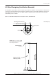
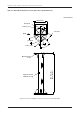
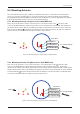
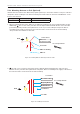

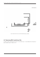
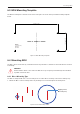
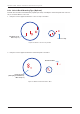
Table Of Contents
- Chapter 1. Precautions
- Chapter 2. Certifications
- Chapter 3. Introduction
- Chapter 4. Planning Installation
- Chapter 5. Installing ADU
- Chapter 6. Installing BDU
- Chapter 7. Operating BDU
- Chapter 8. Using AptusLX
- Chapter 9. Specification
- Chapter 10. Warranty
- Chapter 11. Appendix
- Chapter 1. Precautions
- Chapter 4. Planning Installation
- Chapter 5. Installing ADU
- Figure 9: Antenna Dimensions
- Figure 10: ADU Mounting Template
- Figure 11: Recommended Mast Design using Inner Holes (with M6 Bolts)
- Figure 12: Recommended Mast Design using Outer Holes (with M10 Bolts)
- Figure 13: Mounting Antenna using Inner Holes (with M6 Bolts)
- Figure 14: Mounting Antenna using Outer Holes (with M10 Bolts)
- Figure 15: Installing 40A Pole Bushing inside Pole Tube
- Figure 16: Installing Pole Bracket
- Figure 17: Mounting Antenna on Pole Mounted Bracket
- Figure 18: Vent Hole
- Figure 19: Connecting RF Cable using Inner Holes (with M6 Bolts)
- Figure 20: Connecting RF Cable using Outer Holes (with M10 Bolts)
- Chapter 6. Installing BDU
- Figure 21: BDU Dimensions (Direct Mounting Type)
- Figure 22: BDU Dimensions (19-inch Rack Mounting Type_Optional)
- Figure 23: BDU Mounting Template
- Figure 24: Direct Mounting of BDU
- Figure 25: Attach Connector Tray to BDU
- Figure 26: Attach Rackmount Plate to BDU
- Figure 27: Intellian C700 System with Connected Devices
- Figure 28: BDU Back Panel View
- Figure 29: LAN Ports (RJ45) Pinout
- Figure 30: Phone Port (RJ14 & 6P4C) Pinout
- Figure 31: Using Cable Splitter with RJ14 Phones
- Figure 32: GPIO Connector Pinout
- Figure 33: Power Connector Pinout
- Figure 34: BDU to Antenna Cable Connection
- Figure 35: Grounding Stud Connection
- Chapter 7. Operating BDU

24
Intellian C700 - Marine Satellite Communication System
5.4.3 Mounting Antenna on Pole (Optional)
Intellian offers the Antenna Pole Mount Kit (separate purchase) to mount the antenna on the pole. The kit is
designed to work on 40A pole. The kit has mounting holes that match the inner hole with M6 bolts on the
bottom of the antenna.
Name (A) Diameter (inch) External Diameter (mm)
40A 1½
48.6
1. When mounting antenna on the 40A pole, the 40A pole bushing needs to be installed inside pole tube
additionally.
A
The one hole of the pole tube must be aligned with the BOW direction. Place the 40A
pole bushing inside pole tube, then tighten them on the
top end of the 40A pole using bolts. Before
assembling bolts, apply Loctite #263 to the bolt's threads to ensure the bolts are fastened rmly.
*The pole tube Inner Diameter is Ø52 mm.
2.
A
The end of one leg of the pole bracket must be aligned with the BOW direction. Place the pole
bracket onto the pole tube then tighten them using bolts. Before assembling bolts, apply Loctite #263 to
the bolt's threads to ensure the bolts are fastened rmly.
M6 x 20L Hex. Bolt
M6 Spring Washer
M6 Flat Washer
x four times
Pole Bracket
Pole Tube
Use a torque wrench.
BOW
A
Figure 15: Installing 40A Pole Bushing inside Pole Tube
Figure 16: Installing Pole Bracket
Use a torque wrench.
x Three Times
M12 x 12L
Socket Set Screw
40A Pole Bushing
*Pole Tube
40A Pole
BOW
A