
User's Guide
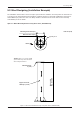
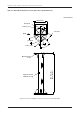
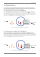
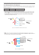

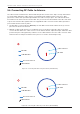
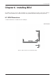
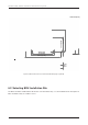
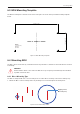
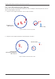
Table Of Contents
- Chapter 1. Precautions
- Chapter 2. Certifications
- Chapter 3. Introduction
- Chapter 4. Planning Installation
- Chapter 5. Installing ADU
- Chapter 6. Installing BDU
- Chapter 7. Operating BDU
- Chapter 8. Using AptusLX
- Chapter 9. Specification
- Chapter 10. Warranty
- Chapter 11. Appendix
- Chapter 1. Precautions
- Chapter 4. Planning Installation
- Chapter 5. Installing ADU
- Figure 9: Antenna Dimensions
- Figure 10: ADU Mounting Template
- Figure 11: Recommended Mast Design using Inner Holes (with M6 Bolts)
- Figure 12: Recommended Mast Design using Outer Holes (with M10 Bolts)
- Figure 13: Mounting Antenna using Inner Holes (with M6 Bolts)
- Figure 14: Mounting Antenna using Outer Holes (with M10 Bolts)
- Figure 15: Installing 40A Pole Bushing inside Pole Tube
- Figure 16: Installing Pole Bracket
- Figure 17: Mounting Antenna on Pole Mounted Bracket
- Figure 18: Vent Hole
- Figure 19: Connecting RF Cable using Inner Holes (with M6 Bolts)
- Figure 20: Connecting RF Cable using Outer Holes (with M10 Bolts)
- Chapter 6. Installing BDU
- Figure 21: BDU Dimensions (Direct Mounting Type)
- Figure 22: BDU Dimensions (19-inch Rack Mounting Type_Optional)
- Figure 23: BDU Mounting Template
- Figure 24: Direct Mounting of BDU
- Figure 25: Attach Connector Tray to BDU
- Figure 26: Attach Rackmount Plate to BDU
- Figure 27: Intellian C700 System with Connected Devices
- Figure 28: BDU Back Panel View
- Figure 29: LAN Ports (RJ45) Pinout
- Figure 30: Phone Port (RJ14 & 6P4C) Pinout
- Figure 31: Using Cable Splitter with RJ14 Phones
- Figure 32: GPIO Connector Pinout
- Figure 33: Power Connector Pinout
- Figure 34: BDU to Antenna Cable Connection
- Figure 35: Grounding Stud Connection
- Chapter 7. Operating BDU

23
Installing ADU
5.4 Mounting Antenna
The lower radome has two types of industry-standard mounting holes, each with four mounting points.
Select one of the two mounting types to secure the antenna to the desired mounting surface. Bring the
provided Antenna Mounting Template and the Bolts from the BDU box. Create the appropriate hole pattern
in the desired mounting surface for the chosen mounting bolts type.
5.4.1 Mounting Antenna using Inner Holes (with M6 Bolts)
First, remove the protective stickers on the Inner Holes. Check the position of the
A
antenna's cable
connector and BOW direction. Lift the antenna above the mounting surface using hands and carefully put
the antenna down in place. Before assembling bolts, apply Loctite #263 to the bolt's threads to ensure the
bolts are fastened rmly.
B
Insert the bolts and washers from under the mast into the radome, and fasten
them to the nuts assembled inside the radome using the torque wrench.
5.4.2 Mounting Antenna using Outer Holes (with M10 Bolts)
First, remove the protective covers on the Outer Holes. Check the position of the
A
antenna's cable
connector and BOW direction. When placing the antenna on the mounting surface, be careful of the
direction of the cutting holes. Lift the antenna above the mounting surface using hands and carefully put the
antenna down in place. Before assembling bolts, apply Loctite #263 to the bolt's threads to ensure the bolts
are fastened rmly.
B
Insert the bolts and washers from under the mast into the radome, and fasten them
to the nuts assembled inside the radome using the torque wrench.
BOW
Use a torque wrench.
x four times
M6 Flat Washer
M6 Spring Washer
M6 x 20L Hex. Bolt
A
B
Use a torque wrench.
M10 Flat Washer
M10 Spring Washer
M10 x 20L Hex. Bolt
B
x four times
BOW
A
Figure 14: Mounting Antenna using Outer Holes (with M10 Bolts)
Figure 13: Mounting Antenna using Inner Holes (with M6 Bolts)