
User's Guide
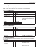
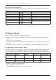
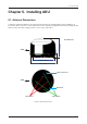
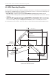
Table Of Contents
- Chapter 1. Precautions
- Chapter 2. Certifications
- Chapter 3. Introduction
- Chapter 4. Planning Installation
- Chapter 5. Installing ADU
- Chapter 6. Installing BDU
- Chapter 7. Operating BDU
- Chapter 8. Using AptusLX
- Chapter 9. Specification
- Chapter 10. Warranty
- Chapter 11. Appendix
- Chapter 1. Precautions
- Chapter 4. Planning Installation
- Chapter 5. Installing ADU
- Figure 9: Antenna Dimensions
- Figure 10: ADU Mounting Template
- Figure 11: Recommended Mast Design using Inner Holes (with M6 Bolts)
- Figure 12: Recommended Mast Design using Outer Holes (with M10 Bolts)
- Figure 13: Mounting Antenna using Inner Holes (with M6 Bolts)
- Figure 14: Mounting Antenna using Outer Holes (with M10 Bolts)
- Figure 15: Installing 40A Pole Bushing inside Pole Tube
- Figure 16: Installing Pole Bracket
- Figure 17: Mounting Antenna on Pole Mounted Bracket
- Figure 18: Vent Hole
- Figure 19: Connecting RF Cable using Inner Holes (with M6 Bolts)
- Figure 20: Connecting RF Cable using Outer Holes (with M10 Bolts)
- Chapter 6. Installing BDU
- Figure 21: BDU Dimensions (Direct Mounting Type)
- Figure 22: BDU Dimensions (19-inch Rack Mounting Type_Optional)
- Figure 23: BDU Mounting Template
- Figure 24: Direct Mounting of BDU
- Figure 25: Attach Connector Tray to BDU
- Figure 26: Attach Rackmount Plate to BDU
- Figure 27: Intellian C700 System with Connected Devices
- Figure 28: BDU Back Panel View
- Figure 29: LAN Ports (RJ45) Pinout
- Figure 30: Phone Port (RJ14 & 6P4C) Pinout
- Figure 31: Using Cable Splitter with RJ14 Phones
- Figure 32: GPIO Connector Pinout
- Figure 33: Power Connector Pinout
- Figure 34: BDU to Antenna Cable Connection
- Figure 35: Grounding Stud Connection
- Chapter 7. Operating BDU

15
Planning Installation
4.2.3 Packing List
Before beginning installation, make sure you have all the included components.
The ADU Package & BDU Package are provided in one box.
NOTE: The SIM card is provided by the service provider and may be packaged separately.
Above Deck Unit (ADU) Package
Description Q'ty Size Remarks
Above Deck Unit (ADU) 1
370 mm x 370 mm x
270 mm
Antenna Unit
LMR200 RF Cable
(TNC/F-TNC/F Type)
1 25 m To connect ADU - BDU
Antenna Mounting Template 1 Antenna Mounting Template
Hex Bolt 5 M6 x 20L
To Mount Antenna on Mounting Surface
(M6 Bolt Kit)
Spring Washer 5 M6
Flat Washer 5 M6
Hex Bolt 5 M10 x 20L
To Mount Antenna on Mounting Surface
(M10 Bolt Kit)
Spring Washer 5 M10
Flat Washer 5 M10
Below Deck Unit (BDU) Package
Description Q'ty Size Remarks
Below Deck Unit (BDU) 1
315 mm x 190 mm x
42 mm
Antenna Control Unit
DC Power Cable 1 1 m BDU Power
Wire Connector 3 For DC Power Cable Extension
Ethernet Cable (RJ45 / LAN) 1 1 m To connect BDU to PC
Wi-Fi Antenna 1
Quick Installation Guide (QIG) 1 Quick Installation Guide
Tapping Screw 5 M5 x 16L To Fix BDU (Direct Mounting Type)
19-inch Rack Mount Kit (Optional)
The 19-inch Rack Mount Kit can be purchased separately. When this kit is supplied, it is packaged in the
BDU Package.
Description Q'ty Size Remarks
Rackmount Plate 1
Kit for Rackmount Plate
Pan Head Screw (with Spring
& Flat Washer)
5 M4 x 16L
Connector Tray 1
Kit for Connector Tray
Flat Head Screw 4 M3 x 6L