
User's Guide
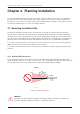
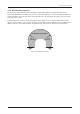
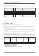
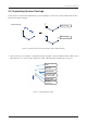
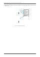
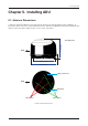
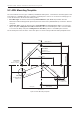
Table Of Contents
- Chapter 1. Precautions
- Chapter 2. Certifications
- Chapter 3. Introduction
- Chapter 4. Planning Installation
- Chapter 5. Installing ADU
- Chapter 6. Installing BDU
- Chapter 7. Operating BDU
- Chapter 8. Using AptusLX
- Chapter 9. Specification
- Chapter 10. Warranty
- Chapter 11. Appendix
- Chapter 1. Precautions
- Chapter 4. Planning Installation
- Chapter 5. Installing ADU
- Figure 9: Antenna Dimensions
- Figure 10: ADU Mounting Template
- Figure 11: Recommended Mast Design using Inner Holes (with M6 Bolts)
- Figure 12: Recommended Mast Design using Outer Holes (with M10 Bolts)
- Figure 13: Mounting Antenna using Inner Holes (with M6 Bolts)
- Figure 14: Mounting Antenna using Outer Holes (with M10 Bolts)
- Figure 15: Installing 40A Pole Bushing inside Pole Tube
- Figure 16: Installing Pole Bracket
- Figure 17: Mounting Antenna on Pole Mounted Bracket
- Figure 18: Vent Hole
- Figure 19: Connecting RF Cable using Inner Holes (with M6 Bolts)
- Figure 20: Connecting RF Cable using Outer Holes (with M10 Bolts)
- Chapter 6. Installing BDU
- Figure 21: BDU Dimensions (Direct Mounting Type)
- Figure 22: BDU Dimensions (19-inch Rack Mounting Type_Optional)
- Figure 23: BDU Mounting Template
- Figure 24: Direct Mounting of BDU
- Figure 25: Attach Connector Tray to BDU
- Figure 26: Attach Rackmount Plate to BDU
- Figure 27: Intellian C700 System with Connected Devices
- Figure 28: BDU Back Panel View
- Figure 29: LAN Ports (RJ45) Pinout
- Figure 30: Phone Port (RJ14 & 6P4C) Pinout
- Figure 31: Using Cable Splitter with RJ14 Phones
- Figure 32: GPIO Connector Pinout
- Figure 33: Power Connector Pinout
- Figure 34: BDU to Antenna Cable Connection
- Figure 35: Grounding Stud Connection
- Chapter 7. Operating BDU

12
Intellian C700 - Marine Satellite Communication System
The antenna installation requires precaution and safety measures. Failure to follow the correct installation
process may lead to injury of the installer and/or cause damage to the system. In order to maximize the
performance of the system, a thorough review of this installation guide is strongly recommended, as well as
executing the installation process as it is noted in this manual.
4.1 Selecting Installation Site
The antenna should be placed in an area on-board of the vessel with an unobstructed view extending
from (at least) -30° below the horizontal surface in all azimuth direction. When the antenna is transmitting,
obstacles in way of the beam path will cause decreased satellite signal strength. The antenna unit should
have direct line-of-sight with the desired satellite without any obstacles in the beam path. Certain minimum
distances between the antenna and other onboard devices must also be considered during installation.
Do not place the antenna near to a funnel because smoke deposits can cause corrosion of the antenna. In
addition, the deposit can result in any malfunction of the antenna.
Do not place the antenna where there is a direct spray of seawater to avoid percolating any water into the
vent hole.
Chapter 4. Planning Installation
4.1.1 Avoiding RF Interference
Do not install the antenna near the high power shortwave radar. Most radar transmitters emit RF energy
within an elevation range of -15° to +15°. For this reason, It is recommended to position the antenna at least
4.6 m (15.09 feet) away from any radars (s-band, c-band, and x-band radar up to 50kW).
WARNING
WARNING
Never place the antenna in the beam path of the radar regardless of distance. The high power
shortwave radar may impair its performance or damage the antenna.
Radar
+15°
-15°
Antenna
Antenna
Minimum
4.6 m (15.09 feet)
Figure 2: Potential RF Interference