
User's Manual


Intelibs, Inc. Proprietary and Confidential Page 8
8
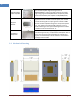
2.1 External interface ports and Status Indicators
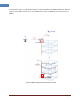
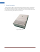
MRU has main interface connections at topside of the enclosure, which includes optic, antennas and dc
power input. The status LEDs and USB port for maintenance are located on left side. Figure 2-2 shows
the top and bottom side of MRU.
Figure 2-2 Top and bottom side of MRU
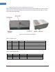
Table 2-1 Interface ports
Port
Connector type
Position
Description
Power
RJ-45
Top
+48V DC inlet, PoE adapter
Debug
USB-A
Left Side
Serial interface for local GUI and debugging
Optic
LC/UPC
Top
Optic fiber connection with FHU or RHU
GPS Out
SMA-Female
Top
GPS signal port to BBU
ANT
4.3-10-Female
Top
Omni ANT connection
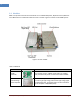
Table 2-2 Status indicator LEDs
Name
Normal state
Abnormal state
Description
Power
Green
Off
Power injection status
RUN
Green/Blinking
Off
CPU working status
Alarm
Green
RED
Major Alarm indication