
User's Manual
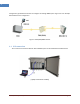

Intelibs, Inc. Proprietary and Confidential Page 26
26
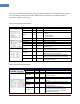
HPA On/Off
√
√
Turn On/Off downlink HPA (High Power
Amplifier).
OUT PWR
√
Display downlink output power to ANT port
OUT UPR
√
√
Set upper limit of downlink output power,
and displays its value and alarm status
OUT LWR
√
√
Set lower limit of downlink output power,
and displays its value and alarm status
ALC
√
√
Set ALC (Automatic Level Control) function’s
activation level, and enable/disable ALC.
ASD
√
√
Set ASD (Automatic Shut Down) function’s
activation level, and enable/disable ASD.
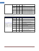
Table 4-3 UL Lower and Upper Band
Status group
Parameters
Status
Control
Description
Protection
On/Off
√
√
Enable/disable uplink protection function.
IN PWR
√
Displays uplink receiving power from ANT
port
IN UPR
√
√
Set upper limit of uplink input power, and
displays its value and alarm status
Pilot
√
√
Enable/disable uplink Pilot signal and selects
uplink CW channel.
ATT
√
√
Set uplink attenuation, and displays its value.
OPWR
√
Displays uplink output power that is
transmitted from MRU
AGC
√
√
Set AGC (Automatic Gain Control) function’s
activation level, and enable/disable AGC.
TC ATT
√
√
Displays uplink temperature compensation
attenuation value, and enable/disable uplink
temperature compensation.
AGC ATT
Displays attenuation value due to AGC
(Automatic Gain Control) operation