
User's Manual


Intelibs, Inc. Proprietary and Confidential Page 25
25
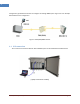
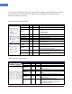
If connection is established successfully, then all parameters of MRU can be set by LMT terminal, and all
status information can be reported to LMT. MRU’s status and parameters controllable by LMT are
described in Table 4-1, 4-2, and 4-3.
Table 4-1 General/Environment/Optic
Status group
Parameters
Status
Control
Description
Version
√
Firmware Version of the Unit
DAS Type
√
The type of the DAS system
Name
√
√
Set following information of the DAS
- Name
- Model Number
- Serial Number
Time/UpTime
√
Current time or Up-time display
User Connect
√
Connection status with RHU
PWR Alarm
√
Display DC Power Alarm
TMPCUR
√
Current chassis temperature of the Unit
TMPUPR
√
√
Set temperature upper limit, and display its value
and alarm status.
LDPWR
√
Current optical output power of LD (Laser Diode)
to transmit to upper unit.
LDLWR
√
√
Set the lower limit of output power of LD, and
display its value and alarm status.
PDPWR
√
Current optical receiving power of PD (Photo
Detector) of optic module connected to MRU.
PDLWR
√
√
Set the lower limit of PD power, and display its
value and alarm status.
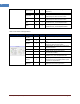
Table 4-2 DL Lower and Upper Band
Status group
Parameters
Status
Control
Description
Lower Band
√
Selects Lower Band (700/850MHz) channel
Upper Band
√
Selects Upper (1900MHz/AWS) channel
Path Use
√
√
Turn On/Off of the usage of this path and
display its status
TOTATT
√
Downlink downlink total attenuation value
USR ATT
√
√
Set user configurable downlink attenuation
value
ALC ATT
√
Attenuation value due to DL ALC function
IN PWR
√
Display the downlink input level coming
from upper unit
TC ATT
√
Displays downlink temperature
compensation attenuation value and
enable/disable downlink temperature
compensation function.