
User's Manual

Intelibs, Inc. Proprietary and Confidential Page 24
24
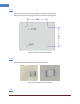
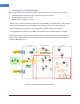
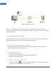
Figure 3-5(b) 2Band Link Antenna and 4CH GPS Antenna connection diagram
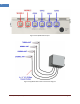
3.6 Power cable
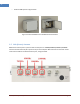
1. The case of PoE Input
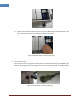
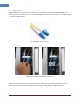
1) Please release gland cap and put Ethernet cable into cap and water protection rubber ring
as following picture.
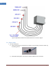
2) Reassemble cable gland to insert Ethernet cable into RHU enclosure as follows.