
User's Manual


Intelibs, Inc. Proprietary and Confidential Page 10
10
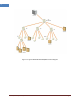
RHU systems with different operating frequency band can be interconnected via over-the-air or RF
Head-End unit. Typical RHU-FHU-SRU/MRU/HRU network diagram is depicted in figure 1-2.
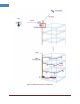
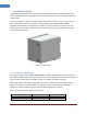
2.2 External interface ports
RHU has all interface connections at bottom side of an enclosure, which includes fiber, antennas and
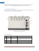
power port. Figure 2-3 shows the bottom side of RHU system.
Figure 2-2 Bottom view of RHU system
Table 2-2 Interface ports
No.
Port
Connector type
Description
1
MOBILE 1 ~ 4
4.3-10 Female
Antenna RF cable connection port for 4-band
2
GPS 1~4
4.3-10 Female
GPS Antenna cable connection port. Two ports of
these ports may be used for Mobile or GPS antenna
connection
3
FIBER
Cable gland
Fiber inlet port
4
PoE
Cable gland
Ethernet cable inlet port for PoE power supply
5
AC POWER
MS Female - 3PIN
120VAC Power cable connector