
User's Manual


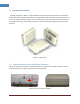
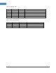
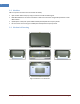
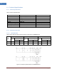
Table Of Contents
- 1 Introduction
- 2 Product Description
- 3 Appendix I. Ancillary Devices – Antenna, Cable and other Passive Device
- 4 Human RF Exposure – Maximum Permissible Exposure Evaluation

Intelibs, Inc Proprietary and Confidential Page 8
8
Table 2-1 Interface ports
Port
Connector type
Position
Description
Power DC Power Jack Top 12V DC inlet, AC/DC converter or PoE adapter
Debug USB Top Serial interface for GUI and debugging
Optic FC/APC Top Optic fiber connection with FHU
LTE SMA-Female Top LTE Uplink/Downlink RF signal interface
ANT SMA-Female Bottom Omni ANT connection
Table 2-2 Status indicator LEDs
Name
Normal state
Abnormal state
Description
Power
Green
Off
Power injection status
RUN
Green/Blinking
Off
CPU working status
Alarm
Green
RED
Major Alarm status