
User's Manual
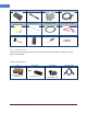
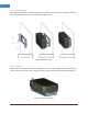
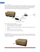
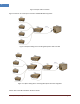
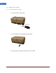
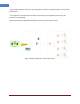
Table Of Contents
- 1 Introduction
- 2 Product Description
- 3 Appendix I. Ancillary Devices – Antenna, Cable and other Passive Device
- 4 Human RF Exposure – Maximum Permissible Exposure Evaluation

Intelibs, Inc Proprietary and Confidential Page 16
16
2.5.6 Power cable
SRU uses 12V DC power, and DC power adapter/splitter set using PoE (Power over Ethernet) technology
are provided with the system. The PoE adapter converts AC input to 48V DC, and delivers DC power via
UTP5 Ethernet cable up to 330 feet. The PoE splitter receives 48V DC power via UTP5 Ethernet cable,
and converts 48V to 12V DC. The power connection diagram is described in Figure 2-8.
Figure 2-8 Power connection
Power connection sequence is as follows:
① Connects UPT5 cable to “OUT” port of PoE adapter.
② Connects UTP5 cable to “IN” port of PoE splitter.
③ Connects one end of power cable to PoE adapter’s AC inlet, and the other side of power cable to
AC outlet.
④ Verify the LED status on PoE splitter and adapter
⑤ Connects DC output connector to “Power” port of SRU.
2.5.7 Optic cable
SRU provides one optic port for uplink, “Optic” port, and optic connector type is FC-APC (Angle Physical
Type). While connecting the optic cable, align the FC type connector at latch and hole position, then plug
in and rotate clockwise tightly.
PoE adapter
PoE splitter
UTP5 cable
(up to 330 feet)
Power