Intelibs, Inc Small Remote Unit Product manual DAS Version : 1.7.
Contents 1 Introduction .......................................................................................................................................... 5 2 Product Description .............................................................................................................................. 7 2.1 External interface ports and Status Indicators ............................................................................. 7 2.2 Modules ............................................
FCC WARNING This equipment generates or uses radio frequency energy. Changes or modifications to this equipment may cause harmful interference unless the modifications are expressly approved in the instruction manual. The user could lose the authority to operate this equipment if an unauthorized change or modification is made. This is NOT a CONSUMER device. It is designed for installation by FCC LICENSEES and QUALIFIED INSTALLER.
CAUTION Any changes or modifications not expressly approved by the manufacturer could void the user's authority to operate the equipment. This equipment is intended for use only with Intelibs Hybrid DAS systems. Important health and safety precautions When using this product, the safety precautions below must be taken to avoid possible legal liabilities and damages. Retain and follow all product safety and operating instructions.
1 Introduction Small Remote Unit (SRU) is part of the Hybrid Distributed Antenna Systems (HDAS) to provide remote RF coverage solution from the Radio Hub Unit (RHU) fed by the RF source via wireline connection.
Figure 1-1 RHU-FHU-SRU/RU network diagram Intelibs, Inc Proprietary and Confidential Page 6
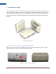
2 Product Description As shown in Figure 2-1, SRU is a compact platform with the natural heat convection. As unified form factor, SRU services multiple technologies on a single platform with Dual band operating frequencies. It can be mounted on the wall, ceiling or 19” rack. Variety of the service antenna can be used from short monopole antenna (e.g. rubber ducky antenna) to indoor multi-band ceiling Omni antenna (or panel antenna). Figure 2-1 SRU system 2.
Table 2-1 Interface ports Port Connector type Position Description Power DC Power Jack Top 12V DC inlet, AC/DC converter or PoE adapter Debug USB Top Serial interface for GUI and debugging Optic FC/APC Top Optic fiber connection with FHU LTE SMA-Female Top LTE Uplink/Downlink RF signal interface ANT SMA-Female Bottom Omni ANT connection Table 2-2 Status indicator LEDs Name Power RUN Alarm Normal state Green Green/Blinking Green Abnormal state Off Off RED Intelibs, Inc Proprieta
2.2 Modules SRU is comprised of several internal modules as follows; • • • • Optic module Performs E/O (or O/E) conversion for FWD and RVS signals. MCU Board Monitors the status of modules in SRU and controls the configurable parameters of the SRU modules. Quadruplexer cavity filter passes FWD and RVS path PCS/Cellular frequency bands. RF Transceiver controls the gain of FWD path of PCS/Cellular frequency bands. 2.
2.4 Technical Specifications 2.4.1 General specifications Table 2-3 General Specifications Specification Dimensions Weight ANT and RF connector Optic port GUI port Input Supply Voltage Operating Temperature Humidity 2.4.2 Values 89(H) x 175.8(W) x 263.8(D) mm 4.6 Kg SMA-type Female FC/APC type USB B-type 12V DC -20 ~ +50 °C 5 ~ 80% Relatively Remarks without holder bracket PoE adapter/splitter Frequency allocation 2.4.2.
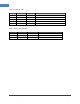
2.4.2.2 850 MHz band Table 2-5 First and last channel center frequency information of 850MHz band GSM 850 Band Edge CH No. WCDMA 850 CH Center freq. (MHz) Down Link Up Link CH No. CDMA 850 CH Center freq. (MHz) Down Link Up Link CH No. CH Center freq. (MHz) Down Link Up Link First CH 128 869.2 824.2 139 871.4 826.4 1013 869.7 824.7 Last CH 251 893.8 848.8 240 891.6 846.6 777 893.31 848.
2.4.3 RF specifications Table 2-6 Dual band specifications Item Specification Downlink Frequency Uplink Frequency 869 ~ 894 MHz, 1930 ~ 1990 MHz 824 ~ 849 MHz, 1850 ~ 1910 MHz Cellular: 25MHz BW PCS: 60MHz BW +26dBm/composite @ANT Port SRU: DL 1310/UL 1550nm 0dB w/ passive device loss 2dBo (2Km) max. 2 dB Peak to Peak +/- 2dB(4dBp-p) 0 ~ 30dB 1 dB 1.5: 1 Max. ±0.01 ppm 500nsec max. 5% max. 0.998 min.
2.5 Installation 2.5.
Torque Wrench Torque Wrench ESD Gloves 4ea of 5m SMA cable FC/APC-SC/APC Optic Fiber, 10m Ground wire line 2ea of ANT RF Cable Wire Stripper & Cutter Rubber Mallet Digital Multi-meter Screw Driver Optic connector cleaner 2.5.3 Item Check List Check that all the following items have been included with the box delivered. If anything is missing, please contact Intelibs.
2.5.4 Wall Mounting SRU supports wall mount. The following diagrams illustrate the methods for mounting SRU in a typical wall. The brackets for wall mount are provided with SRU system. Figure 2-6 Wall mounting 2.5.5 Antenna SRU uses various antennas depends on its application and environment. SRU provides one antenna port “ANT” at the rear side of the system. Figure 2-9 shows antenna connection with swivel blade antenna.
2.5.6 Power cable SRU uses 12V DC power, and DC power adapter/splitter set using PoE (Power over Ethernet) technology are provided with the system. The PoE adapter converts AC input to 48V DC, and delivers DC power via UTP5 Ethernet cable up to 330 feet. The PoE splitter receives 48V DC power via UTP5 Ethernet cable, and converts 48V to 12V DC. The power connection diagram is described in Figure 2-8.
Figure 2-9 Optic cable connection Figure 2-10 and 2-11 shows optic connection of RHU-FHU-SRU equipment. Figure 2-10 Optic cabling when cascading DAS systems with one FHU Figure 2-11 Optic cabling when cascading DAS systems with two-stage FHU Please refer to the SRU Installation Guide for details.
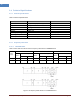
2.6 SRU power setting 2.6.1 Down Link power setting 1. Connect the power cable to SRU Power PoE splitter 2. Connect USB cable to manage SRU through Laptop. 3.
② ① ③ ④ 4. Decrease the DL “USER ATT(①)” to 30dB(Minimum gain) and verify that antenna is connected at antenna port of SRU properly. 5. Press the “HPA On/Off(②)” button to turn HPA on 6. Monitor the output power level from “ OUT PWR(③)” parameter and tune up “USR ATT(①)” to set the proper output power level of SRU. 2.6.2 Up Link power setting 1. Use the “ATT(④)” to control Uplink gain. 2. Uplink gain is very important parameter because uplink is connected to RF source of BTS.
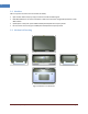
LMT (Local Management Terminal) is local management interface through IP network, serial interface, and Bluetooth. The configuration and maintenance for SRU is performed by accessing RHU system through any interfaces provided by RHU. Figure below describes a typical DAS management system network and the entities.
Table 2-10 DAS management entities and their functions Functions On-site Installation SNMPv3 Web Serial interface o IP address assignment o ID assignment (for Remote Unit) o System Password o System Registration System Registration/Unregister Site/Location setting DAS system’s site and location information o Capture and restore the configuration o Remote/Local management o Parameters settings and retrieval o F/W upgrade o Alarms o Alarm history Alarms User management LMT o
2.7.1.1 Configuring FHU/SRU If one of Bluetooth or Ethernet connection has been established, LMT is ready to start. Launch the Local Management application by clicking the icon “Cherry” and follows the steps below. Step 1 • • • Launch the application “Cherry”. Enter the password, click “Login”. Click “Connect” icon on the left top corner of window.
• Click “Select Done” button. Step 3 • If “Repeater Browser” window appears, click DUAL-SRHU system. Step 4 • Select “Install Remote” tab to install FHU and SRU, then click “Refresh” button. Step 5 • • • At “Repeater Network Configuration” window, click “click to add” text. In the “Install Information” select “FHU”. Select FHU ID from the FHU drop down list. FHU’s ID is provided by manufacturer.
Step 6 • • • If FHU’s ID is selected, click “Install” button at “Install Information”. After Install, click “Refresh” button to display installed equipment. If FHU is installed properly, at “FHU Install / Link Status“ panel a check box on the left side of FHU’s ID turns to GREEN, otherwise it turns to RED. Step 7 • Click “click to add” text on FHU’s port that SRU attached, then select “SRU” and click drop-down box to select SRU’s ID. SRU’s ID is provided by manufacturer.
If SRU’s ID is chosen, then press “Install” button. After Install, press “Refresh”. If SRU is installed properly, a small box on the left side of SRU’s ID turns to GREEN, otherwise it turns to RED. • • Step 9 • At “Repeater Browser” window, click the DAS system to be managed, then the selected DAS system’s control window will pop up. If connection is established successfully, then all parameters of SRU can be set by LMT terminal, and all status information can be reported to LMT.
Time/UpTime User Connect PSU TMPCUR √ √ TMPUPR √ LDPWR √ √ LDLWR √ √ PDPWR √ PDLWR √ √ LED Clickable √ √ - Serial Number Current time or Up-time Connection status with the DAS Status of Power Supply Unit Current chassis temperature of the DAS system Set temperature upper limit, and display its value and alarm status. Current output power of LD (Laser Diode) of optic module connected to SRU. Set the lower limit of output power of LD, and display its value and alarm status.
IN UPR √ √ CW √ √ ATT OPWR √ AGC √ √ TC ATT √ √ AGC ATT Intelibs, Inc Proprietary and Confidential Set upper limit of uplink input power, and displays its value and alarm status Enable/disable uplink Pilot, and selects uplink CW channel. Set uplink attenuation, and displays its value. Uplink output power Set AGC (Automatic Gain Control) function’s activation level, and enable/disable AGC.
2.7.1.2 Setting the Temperature Upper Limit Following is one example of LMT operation which sets the upper limit of SRU chassis’ temperature. Step 1 • • At “Repeater Browser” window, click the DAS system to be managed, then the selected DAS system’s control window will pop up. Click the temperature upper limit box which is on the right side of “TMPUPR”. A number in the box represents current upper limit of chassis’ temperature.
The small color box on the left side of “TMPUPR” represents current status of upper limit of SRU chassis’ temperature. If the box is GREEN, operating status is in normal condition. If the box is RED, “TMPUPR” alarm occurred and remains. 2.7.2 Web interface Master Unit provides comprehensive management of the Intelibs optical DAS systems via Web GUI.
• • • • • • • Alarms: Current alarms of all registered DAS systems. SNMP settings: SNMP environment settings such as trap IP, community, V3 user, etc. Site settings: Assign site and location information to each registered Das systems. User settings: Add/delete web user and change user’s password Support: Intelibs’ support information. About us: Redirect to Intelibs’ web page. Log Off: Logging off current user’s session.
• Enter Master Unit’s IP address that is assigned for Web interface. Usually the IP address is global IP or private IP if web client is on the same network where Master Unit is. Step 2 • Enter Login ID and Password. (Please contact Intelibs for login ID and password) The web interface provides two level user access, privileged or not. Privileged users can retrieve and change the advanced parameters that control the DAS system.
Step 3 • Click “DAS systems” menu box to see the Hierarchy view of DAS systems.
Step 4 • Select a DAS system to control and monitor at the hierarchy view. Step 5 • Select “Advanced Mode” check box to display advanced parameters, for example “Chassis High Temperature Alarm Threshold” in the parameter view panel.
Step 6 • Enter numbers for “Chassis High Temperature Alarm Threshold”. Then click “Set” button. Step 7 • If confirmation window pops up, click “OK” button to confirm changing the parameter value. • Then result window will pop up. The column “Chassis High Temperature Alarm” represents upper limit of SRU chassis’ temperature. If the value box is GREEN, operating status is in normal condition. If the box is ORANGE, this indicates “TMPUPR” alarm is turned on.
3 Appendix I. Ancillary Devices – Antenna, Cable and other Passive Device Intelibs does not provide the ancillary device, however the following or equivalent devices are recommended: • Recommended Antenna: o Larson Dipole Antenna o Commscope Electrical Specifications Frequency Band, MHz Gain, dBi Beamwidth, Horizontal, degrees VSWR | Return Loss, dB Input Power per Port, maximum, watts Polarization Impedance • 698–800 1.5 360 1.8 | 10.9 50 Vertical 50 ohm 800–960 1.5 360 1.5 | 14.
Phihong PoE Adaptor (POE61U-560DG-R) and Splitter (POE-45-120-R) or equivalent products • • Coaxial Cable: o RG142 or equivalent coaxial cables Fiber Cable: o FC/APC optical cable Intelibs, Inc Proprietary and Confidential Page 36
4 Human RF Exposure – Maximum Permissible Exposure Evaluation The recent FCC developed guideline for evaluation of the human exposure to the RF emissions. The maximum permission Exposure (MPE) for power density of the transmitter operating RF ranges between 300 KHz and 100 GHz. As the Intelibs SRU belongs to the fixed equipment, Analysis has been conducted to evaluate the MPE from the distance greater than 20 Cm as the fixed equipment required. Antenna gain is restricted to 1.5W ERP (2.
Limited Warranty Intelibs, Inc (“Intelibs”) offers a standard two year warranty from defects in material and installation.
Index AC Power specifications ................................... 12 Advanced Mode ............................................... 34 AGC .................................................................. 28 Alarm history.................................................... 30 Bluetooth ................................................... 19, 22 DAS management network .............................. 20 DAS Type .......................................................... 27 FC-APC ..........................
Contact: supports@intelibs.com Address: Intelibs, Inc. 1500 Stony Brook road, Stony Brook, NY 11794 Web: http://www.intelibs.