Installation/User’s Guide AMT 8000 LITE
AMT 8000 LITE Alarm center Congratulations, you have just purchased a product with Intelbras quality and safety. The AMT 8000 LITE wireless alarm center features advanced technology and is easy to program. All 8000 series devices can be connected, exchanging encrypted information, for increased system security.
Care and Safety » Follow all instructions in the manual to install and handle the product. » Install in environments not susceptible to factors such as rain, fog and water splashes. » Wireless communication technology, when exposed to environments with high power radiation, may suffer interference and and have its performance impaired. Example: locations near TV towers, AM/FM radio stations, amateur radio stations, etc.
Summary 1. Installation 5 2. Enter programming mode 7 2.1. Enter programming mode. . . . . . . . . . . . . . . . . . . . . . . . . . . . . . . . . . . . . . . . . . . . . . . . . . . . . . . . . . . . . . . . . . . . .7 2.2. Exit programming mode . . . . . . . . . . . . . . . . . . . . . . . . . . . . . . . . . . . . . . . . . . . . . . . . . . . . . . . . . . . . . . . . . . . . .7 3. Quick programming reference 7 3.1. Wireless devices . . . . . . . . . . . . . . . . . . . . . . . . . . . . . . . . .
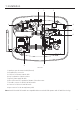
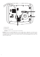
1. Installation 1 2 9 3 AMT 8000 LITE/PRO 4 5 6 7 8 Front view 1. 2. 3. 4. 5. 6. 7. 8. 9. Opening to pass the network cable (Ethernet). Integrated siren connection. Connector for Ethernet network cable. Key for registration of wireless devices. Input for power supply flat cable. Micro-USB connector to update the firmware of the alarm center. Flat cable connector for XG 2G / XG 3G modules. Connector for SIM card 1 and SIM card 2. Input connector for the two-way battery cable.
1 AC AC 2 3 1. Tamper-proof key. 2. Integrated siren. 3. Connector for AC power supply. Attention: be careful not to reverse the position of the ground wire.
2. Enter programming mode Note: to modify the technical parameters of your alarm center, it is recommended to contact a qualified technician. 2.1. Enter programming mode To modify any of the center’s operating parameters, always enter the programming mode. To do this, enter the following sequence: Enter + Password (Master or Installer Password) 2.2. Exit programming mode To exit programming mode, enter the master password or the installer password (the same password used to access programming mode). 3.
» Register the wireless keyboard Enter + 620 + NT + Enter + Actuate the keypad by pressing the synchronization key. NT = keyboard number from 01 to 16. » Delete wireless keyboards Enter + 720 + NT + Enter. NT = keyboard number from 01 to 16. » Keyboard firmware preview Enter + 642 + TT + Enter TT = 2-digit keypad number Note: function available for keyboards from version 2.0.0 onwards. » Wireless keyboard partitioning Enter + 223 + NT + PP + Enter. NT = keyboard address from 01 to 16.
Remote control » Remote control registration Enter + 60 + NU + Enter + Actuate the control by pressing one of the keys. NU = user number from 00 to 97. » Delete remote control Enter + 70 + NU + Enter. NU = user number from 00 to 97. » Remote control key functions Enter + 65 + T + NU + FC + Enter. T = control key from 1 to 3. NU = user number from 00 to 97. FC = function of the key that will be linked to the selected key from 00 to 66.
40 41 42 43 44 45 46 51 52 53 54 55 56 57 58 59 60 61 62 63 64 65 66 Atv/Dtv partial mode only for Partition 10 Atv/Dtv partial mode only for Partition 11 Atv/Dtv partial mode only for Partition 12 Atv/Dtv partial mode only for Partition 13 Atv/Dtv partial mode only for Partition 14 Atv/Dtv partial mode only for Partition 15 Atv/Dtv partial mode only for Partition 16 PGM 01 PGM 02 PGM 03 PGM 04 PGM 05 PGM 06 PGM 07 PGM 08 PGM 09 PGM 10 PGM 11 PGM 12 PGM 13 PGM 14 PGM 15 PGM 16 Wireless sensors » Register
» Restoring the digital tamper of the IVP 8000 EX sensor Enter + 543 + ZZ+ Enter. ZZ= 2-digit zone number. » Display of sensors firmware Enter + 641 + ZZ + Enter. ZZ = 2-digit zone number. Note: function is available for devices with version 2.0.0.0 and higher. For devices with a version lower than 2.0.0.0, 0.0.0.0 will be displayed. Wireless sirens » Register wireless sirens Enter + 621 + NS + Enter + Actuate the siren by pressing the synchronization key. NS = siren number from 01 to 16.
» Repeater firmware verification Enter + 644 + RR + Enter. RR = 2-digit repeater number. Route change by command » Search for new route sensors Enter + 544 + ZZ + Enter. ZZ = 2-digit zone number. » XAT 8000 new route search Enter + 545 + TT + Enter. TT = 2-digit keypad number. » PGM 8000 new route search Enter + 547 + PP + Enter. PP = 2-digit PGM number. Note: function available for devices from version 2.0.0 onwards.
» Days for Programmed auto-activation of PGM 8000 Actuator Enter + 836 + PGM + Enter. PGM = PGM number from 01 to 16. After the command, with the keyboard keys, select the days of the week from 1 to 7, where 1 = Sunday, 2 = Monday, 3 = Tuesday, 4 = Wednesday, 5 = Thursday, 6 = Friday, 7 = Saturday and 8 = holiday and confirm with Enter. » Time of auto-activation of the PGM 8000 Actuator Enter + 561 + PGM + D + HH + MM + Enter. PGM = PGM number from 01 to 16.
3.2. Ethernet/GPRS connection » Ethernet: An RJ45 type cable must be installed in the center with the Ethernet signal coming from a router, switch or directly from the signal received at the installation site. Check with the Internet provider whether the port used allows external access.
» Program DNS servers for Ethernet Enter + 815 + S + Enter, where S = 1 or 2 (Server 1 or Server 2). After the command, type the DNS1 server number and press the Enter key to confirm. 3.3. Remote update To download/check out a new version Enter + 9922 + Enter. If there is a version available for download, the message Download Wait will appear and the download will start, which will take between 3 and 5 minutes (depending on the network).
» Define permission for partial mode Enter + 221 + GS + Enter + Select password + Enter. GS = group of passwords from 0 to 9, with group 0 going from 01 to 10, group 1 from 11 to 20 and so on closing with group 9 from 91 to 97. 3.5. Zone configuration Enable/disable zones Enter + 30 + G + Enter. G = group of zones from 0 to 6. After entering the command, using the keyboard keys, enable/disable the corresponding zones for the group and press the Enter key to confirm.
On input partition Enter + 516 + GP + Enter GP = group of partitions, with partitions 01 to 10 in group 0 and partitions 11 to 16 in group 1. Permission to activate and/or deactivate the oninput Enter + 518 + Enter Tecla 2 – Permission to activate Tecla 3 – Permission to deactivate 3.6. Partition Enable partition Enter + 510 + Enter + Select option 1 + Enter. Zone partitioning Enter + 01 + ZZ + PP + Enter. ZZ = zone from 01 to 64. PP = partition from 01 to 16.
Disable the output beep Enter + 514 + Enter + Key 8 + Enter. 3.8. Temporary configuration of the alarm center Clock Enter + 400 + HH + MM + SS + Enter. HH = hours from 00 to 23. MM = minutes from 00 to 59. SS = seconds from 00 to 59. Calendar Enter + 401 + DD + MM + AA + Enter. DD = day from 01 to 31. MM = month from 01 to 12. YY = year from 00 to 99. Setting the day of the week Enter + 402 + D + Enter.
Day of the week auto activation Enter + 838 + PP + Enter. PP = partition from 01 to 16 (center without partition, use PP = 01). After the command, use the keyboard keys to select the days of the week from 1 to 7, where 1 = Sunday, 2 = Monday, 3 = Tuesday, 4 = Wednesday, 5 = Thursday, 6 = Friday, 7 = Saturday. Auto activation schedule Enter + 462 + PP + D + HH + MM + Enter. PP = partition from 01 to 16 (center without partition, use PP = 01).
Via Ethernet » Program monitoring account Enter + 15 + PP + Enter, where PP = partition from 01 to 16. After the command: type the 4-digit monitoring account number (0 to 9 or the letters B, C, D, E and F) and press the Enter key to confirm. If the center is not partitioned, use the partition as 01. » Program the report mode Enter + 17 + AAA + Enter. AAA = indicates in which mode the alarm center will operate, where 000: disabled, 400: regular IP and 600: dual IP.
» Program DNS servers for Ethernet Enter + 815 + S + Enter, where S = 1 or 2 (Server 1 or Server 2). After the command, type the DNS1 server number and press the Enter key to confirm. » Program Ethernet heartbeat interval (link test) Enter + 816 + TTM + Enter, where TTM = time interval ranging from 000 to 255 minutes (default: 5 minutes). » Exit programming mode with the installer’s password Installer password (default: 9090).
» Program password Enter + 823 + O + Enter, where O = 1 or 2 (operator 1 or operator 2). After the command, type the password (according to the operator used) and then press the Enter key to confirm. » Programar APN Enter + 824 + O + Enter, where O = 1 or 2 (operator 1 or operator 2). After the command, type the APN (according to the operator used) and then press the Enter key to confirm.
» Enable/Disable Contact-ID code for zone restore type events Enter + 911 + ZZ + Enter ZZ = zone from 01 to 64 » Enable/Disable Contact-ID code for tamper-open type events Enter + 902 + ZZ + Enter ZZ = zone from 01 to 64 » Enable/Disable Contact-ID for tamper reset type events Enter + 912 + ZZ + Enter ZZ = zone from 01 to 64 » Enable/Disable Contact-ID code for deactivation events by users Enter + 903 + NU + Enter NU = user number from 01 to 97 » Enable/Disable Contact-ID code for activation events by u
» To set up Contact-ID code for restore type system events, type: Enter + 914 + II + Enter II = system event index from 00 to 26 Index 00 01 02 03 05 06 07 08 09 10 11 12 13 14 15 16 17 18 19 20 21 Opening type events System events Internal event Wireless device low battery restoration N/A Restoration of supervision failure Zone bypass restoration AC network restoration Low system battery restoration Battery restoration N/A Remote activation Automatic activation One key activation Activation under duress
Event group (EV) 1 2 3 Event LOW_SENSOR_BATTERY, N/A SUPERVISION_RF_FAILURE, BYPASS_ZONE, AUTOMATIC_BYPASS, ELECTRICAL_NETWORK_FAILURE, LOW_MAIN_BATTERY, ABSENT_MAIN_BATTERY, N/A REMOTE_ARM_DISARM, AUTO_ARM_DISARM, QUICK_ARM, ARM_DISARM_UNDER_DURESS, SYSTEM_RESET, PROGRAMMING_CHANGED, FAILURE_TO_COMMUNICATE_EVENT, WRONG_PASSWORD, ACCESS_DOWNLOAD, MANUAL_TEST, PERIODIC_TEST, RESET_BUFFER_EVENTS, RESET_DATE_TIME, TAMPER_KEYBOARD TAMPER_SIREN MAINTENANCE_REQUEST, Key Tecla 1 Tecla 2 Tecla 3 Tecla 4 Tecla
3.13. Failure delivery time AC failure Enter + 481 + TM + Enter. TM = failure delivery time from 01 to 99 minutes. 3.14. System reset Reset of the whole system, except for the registration of wireless devices. Enter + 0000 + Enter. 3.15. Reset of the whole system Programming, messages and wireless devices Enter + 9999 + Enter. 3.16.
Warranty Terms It is hereby expressly stated that this contractual warranty is conferred under the following conditions: Name of client: Client’s signature: Invoice No.: Date of purchase: Model: Serial No.: Retailer: 1.
Customer Support: (48) 2106 0006 Forum: forum.intelbras.com.br Support via chat: chat.intelbras.com.br Support via e-mail: suporte@intelbras.com.br Customer Service: 0800 7042767 Where to buy? Who installs it? 0800 7245115 Produced by: Intelbras S/A – Indústria de Telecomunicação Eletrônica Brasileira Rodovia BR 459, km 124, 1325 – Distrito Industrial – Santa Rita do Sapucaí/MG – 37540-000 CNPJ 82.901.000/0016-03 – www.intelbras.com.br | www.intelbras.com 02.