XP-P5CM-GV/ XP-P5CM-GL Intel® Pentium® 4 LGA775 Processor Motherboard User's Manual M-050501
Copyright Declaration © 2005 Gigatrend Technology Co., Ltd. All rights reserved. No part of this manual may be reproduced, copied, translated, or transmitted in any form or by any means without express permission from Gigatrend Technology. Companies and product names mentioned in this document are trademarks or registered trademarks of their respective owners.
Contents Motherboard Layout ......................................................................... 4 1. Product Introduction .................................................................. 5 1.1. Feature Summary ............................................................................. 5 1.2. I/O Back Panel and Connectors&Jumper Setting ........................... 6 1.2.1. I/O Back Panel ....................................................................................... 6 1.2.2.
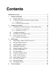
IT8712F KB_MS CPU_FAN COM1 LGA775 FDD VGA LPT ATX_12V ATX Intel 915GV j/ Intel 915GLk SUR_CEN SYS_FAN DIMM1 IDE1 PCIE_16 DIMM2 AUDIO F_AUDIO XP-P5CM LAN USB R_USB BIOS RTL8100C PCI1 ICH6 GLk GEAR -GV j / English Motherboard Layout SATA2 SATA0 CODEC PCI2 CD_IN F_USB1 Only for XP-P5CM-GV. 4 Only for XP-P5CM-GL.
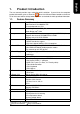
English 1. Product Introduction The user manual provides steps related to quick installation. If you wish to view complete ",open User Manual button located on the driver product information, please select the " CD or link to our website at http://www.axper.com to received the most up-to-date information. 1.1.
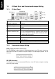
English 1.2. I/O Back Panel and Connectors&Jumper Setting 1.2.1. I/O Back Panel Parallel Port PS/2 Mouse LAN Line In USB Line Out MIC In PS/2 Keyboard COM1 PS/2 Keyboard PS/2 Mouse connector Parallel port (LPT) COM1 (Serial port) VGA port USB (Universal Serial Bus Port) LAN (RJ45 LAN Port) Line In Line Out MIC In 1.2.2.
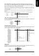
The cooler fan power connector supplies a +12V power voltage via a 3-pin/4-pin(only for CPU_FAN) power connector and possesses a ful-proof connection design. Most coolers are designed with color-coded power connector wires. A red power connector wire indicates a positive connection and requires a +12V power voltage. The black connector wire is the ground wire (GND). Please remember to connect the power to the cooler to prevent system overheating and failure.
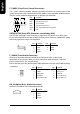
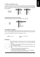
SPK- SPK+ MSG+ MSGPW+ PW- The F_Panel Control Connector connects to certain connectors on the front panel of the system casing such as IDE Hard Disk Active LED, speaker, reset, and power on/off connectors. You can use the schematic diagram below as the basis for connection.
Connects to the USB connector located on the front panel of the system casing (dependent on case design). Note: Please make sure that each USB connection matches its designated position. If connections are made incorrectly, the result can lead to inability to use the function or even damage.
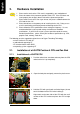
English 2. Hardware Installation 1. Please make sure that the CPU used is supported by your motherboard. 2. Please be aware of the placement position of the CPU. If the CPU does not insert properly, do not apply force but check the placement position. 3. Please make sure that an even layer of heat sink paste is added between the CPU and the fan sink. 4. Please do not turn on the power prior to installing the fan sink. Doing so can result in overheating and lead to permanent damage to the CPU. 5.
2.1.2. Installation of Fan Sink 1. Apply a thin coating of thermal paste to complete cover the surface of the CPU. 2. Align the four fasteners of the fan sink with the four holes around the CPU socket. Push down each fastener and you should hear a "click" when the fastener is attached. Make sure the four fasteners are attached securely. Prior to installation of the fan sink, check the direction of each fastener by the arrow engraved on fastener top.
English 2.2. Installation of Memory 1. Before installing or removing memory, please make sure that the computer power is turned off to prevent hardware damage. 2. Please make sure that the memory used is supported by the motherboard. 3. Memory modules have a foolproof insertion design. The memory can be in stalled only when facing the correct position. If you cannot insert the module, please switch directions. 4. It is recommended that memory of similar capacity, specifications and brand be used.
Installation of the Graphics Card To install or remove an AGP graphics card, first pull out the white GEAR knob before insertion or removal. Releasing the GEAR knob will hold the graphics card firmly in place. 2.4. What is Axper's G.E.A.R.? The revolutionary and innovative G.E.A.R. (GIGABYTE Enhance AGP Riser) interface provides an additional interface for traditional AGP Graphics card on Intel chipset based PCI Express solution motherboard.
English Figure 1-2.
English Figure 3.
English
English 3. BIOS Setup BIOS (Basic Input and Output System) stores all the information of the motherboard settings that is needed for system initiation within the CMOS. The CMOS SETUP utility allows the user to make changes in BIOS configurations that are required or to activate certain features. The CMOS SETUP saves each item configuration in the CMOS SRAM of the motherboard. When the power is turned off, the battery on the motherboard supplies the required power to the CMOS SRAM.
English Gives the list of options available for each item Return to Optimized default values (not applicable to main setup screen) Enters BIOSNow! feature Displays system information Saves settings and exits setup 3.2. Standard CMOS Features ø Includes the settings for items such as date, time, floppy disk drive specifications, and hard drives connected to the IDE interface.
Hard drive information should be labeled on the outside drive casing. Enter the appropriate option based on this information. n Drive A/B Allows user to configure the type of floppy drive his/she installs. Options: None (No floppy drive installed) 360K, 5.25" (5.25 inch PC-type high-density drive; 360K bytes capacity.) 1.2M, 5.25" (5.25 inch AT-type high-density drive; 1.2M bytes capacity.) 720K, 3.5" (3.5 inch double-sided drive; 720K bytes capacity.) 1.44M, 3.5" (3.5 inch double-sided drive; 1.
English 3.3. ø Advanced BIOS Features Allows the configuration of advanced settings such as boot sequence, password check, etc. CMOS Setup Utility-Copyright (C) 1984-2005 Award Software Advanced BIOS Features } Hard Disk Boot Priority [Press Enter] Item Help First Boot Device [Floppy] Menu Level} Second Boot Device [USB-FDD] Third Boot Device [Hard Disk] Select Hard Disk Boot Password Check [Setup] Device Priority # CPU Hyper-Threading [Enabled] Limit CPUID Max.
Allows user to enable the No-Execute Memory Protect function. (default: Enabled) n CPU Enhanced Halt (C1E) (Note) Allows user to enable the CPU Enhanced Halt (C1E) function. (default: Enabled) n CPU Thermal Monitor 2(TM2) (Note) Allows user to enable the CPU Thermal Monitor 2(TM2) function.(default: Enabled) n CPU EIST Function (Note) Allows user to enable the CPU EIST function.(default: Enabled) n On-Chip Frame Buffer Size Allows user to set the size of the on-chip frame buffer.
English n PATA IDE Set to Options: Ch.0 Master/Slave, Ch.1 Master/Slave (default:Ch.0 Master/Slave ) n SATA Port 0/2 Set to This value depends on the settings of "On-Chip SATA Mode" and "PATA IDE Set to". For example, if you set PATA IDE to Ch. 1 Master/Slave, this option will be automatically set to Ch. 0 Master/Slave. n USB Controller Allows the user to enable or disable the onboard USB controller. (default:Enabled) n USB 2.0 Controller Allows the user to enable or disable the onboard USB2.
ø English 3.5. Power Management Setup This is used to control the various power saving features of the PC.
English n KB Power ON Password Allows user to set a 1-5 character long password for powering on the keyboard. Select Enter to complete setting. n AC BACK Function Allows user to select system status when power is removed and returned. Options: Memory (return prior to power removal) Full-On (return to full system power) Soft-Off (use of Soft PWR button to power on system)(default:Soft-Off) 3.6. ø PnP/PCI Configuration This menu allows you to configure your PCI slots.
ø English 3.7. PC Health Status This menu displays the current CPU temperature, the fan speeds, voltages etc. CMOS Setup Utility-Copyright (C) 1984-2005 Award Software PC Health Status Vcore OK Item Help DDR25V OK Menu Level} +3.
English Options: Note: 3.8. ø Auto (BIOS autochecks which type of CPU fan is installed and sets the optimcal CPU Smart FAN control mode.) Voltage (Set this item to Voltage if a 3-pin CPU fan is installed.) PWM (Set this item to PWM if a 4-pin CPU fan is installed.) In fact, you can set the CPU Smart Fan Control mode to Voltage for either 3pin or 4-pin CPU fan.
ø Save & Exit Setup To save any changes you made to the BIOS you must choose this option. The system will automatically exit setup and perform a system restart. Pushing will have the same effect. Push and to save and exit setup. If you do not wish to save, select or to return to the main menu. 3.13. ø Set User Password Use this to set the password that is needed to either enter into the BIOS or to boot the system. Entering in a blank field will disable the password.
English 4. Driver Installation Driver installation for the Windows 2000/XP operating systems is simple. Once you insert the provided driver disks into your optical drive, the AUTORUN screen will appear. If this screen does not appear, you can use "D:\setup.exe" (with "D" being the specified drive) to bring up the screen shown below. Just follow the screen instructions to easily complete driver installation.