
Intel Xeon Processor Multiprocessor Platform Design Guide

85
Processor Power Distribution Guidelines
Since the target of 2/3 of V
CC
is 1.133 V, this setting is within 0.7% of the 2/3 point and satisfies
the 2% specification. A spreadsheet program allows the reader to easily verify the other corners.
Varying over its tolerance range has minimal effect.
These values chosen for R
1
and R
2
have additional benefits: The parallel combination terminates
the GTLREF line to 33 Ω. These generally available resistance values reduce resistor cost.
Decouple GTLREF[3:0] at each pin with a 220 pF capacitor to V
SS
. Decoupling GTLREF to V
SS
at
the voltage dividers with a 1 µF capacitor may further enhance the ability for GTLREF to track
V
CC
.
When routing GTLREF to the pins, use a 30-50 mil trace (the wider the better) and keep it as short
as possible (less than 1.5 inches). Also, keep all other signals at least 20 mils away from the
GTLREF trace. This provides a low impedance line without the cost of an additional plane or
island. Due to the placement of the GTLREF pins on the processor, it may not be possible or
convenient to route all four pins from one voltage divider. It is acceptable to use more than one
voltage divider with decoupling at each voltage divider and each pin.
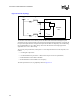
8.13 Filter Specifications for V
CCA
, V
CCIOPLL
, and V
SSA
V
CCA
and V
CCIOPLL
are power required by internal PLL. These powers are low passed filter V
CC
.
Intel Xeon processors MP have internal PLL clock generators, which are analog in nature and
require quiet power supplies for minimum jitter. Jitter is detrimental to a system; it degrades
external I/O timings, as well as internal core timings (i.e., maximum frequency). The general
desired topology is shown in Figure 8-15. Not shown in the figure are the parasitics of connecting
traces, circuits, and components.
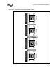
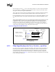
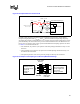
Figure 8-14. Suggested GTLREF Generation
VCC
GTLREF
VSS
49.9Ω with 1% tolerance,
capable of 25 mW power
100Ω with 1% tolerance,
capable of 25 mW power
1µF
Routing distance between voltage
divider and pin should be
less than 1.5[in]
GTLREF Pins
High frequency
capacitors at each
GTLREF
i
Baseboard Routing