
Intel Xeon Processor and Intel E7500/E7501Chipset Compatible Platform Design Guide

Intel
®
Xeon™ Processor and Intel
®
E7500/E7501 Chipset Compatible Platform Design Guide 69
System Bus Routing Guidelines
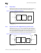
5.3.1 Power Good
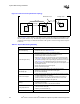
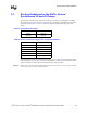
Follow the topology shown in Figure 5-4 when routing power good. Connect the processor
PWRGOOD pin to the ICH3-S CPUPWRGD pin. You may choose to isolate power good for each
voltage regulator and processor pair to recognize individual voltage regulator failures.
NOTES:
1. Trace Z
0
= 50 Ω
2. Trace spacing = 10 mil
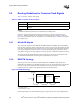
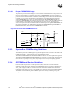
5.3.2 Asynchronous GTL+ Signals Driven by the Processor
Follow the topology shown in Figure 5-5 when routing FERR#/PBE#, IERR#, PROCHOT# and
THERMTRIP#. This topology shows these signals connected in a "wired-OR" configuration,
however, special routing consideration is not required if the layout guidelines in this section are
followed. Note that FERR#/PBE# is the only signal in this group that connects the processors to the
ICH3-S. IERR#, PROCHOT# and THERMTRIP# connect to other motherboard logic
(e.g., the Baseboard Management Controller) and may need voltage translation logic, depending on
the motherboard receiver logic devices used. Do not route a stub when routing to the processors.
NOTES:
1. Trace Z
0
= 50 Ω
2. Trace spacing = 10 mil
Figure 5-4. Topology for PWRGOOD (CPUPWRGOOD)
Intel
®
ICH3-S
Processor 0 Processor 1
0.1" – 3.0"
0.1" – 9.0" 0.1" – 9.0"
VCC_CPU
300 Ω ± 5%
Figure 5-5. Topology for Asynchronous GTL+ Signals Driven by the Processor
Intel
®
ICH3-S
or other logic
Processor 0 Processor 1
VCC_CPU
0.1" – 3.0"
0.1" – 10.0" 0.1" – 10.0" 0.1" – 10.0"
VCC_CPU
56 Ω ± 5%
56 Ω ± 5%