
ITP700 Debug Port Design Guide


R
ITP700 Debug Port Design Guide 19
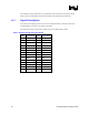
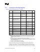
1.4.2 Termination and Routing Guidelines
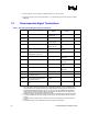
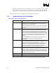
Table 6. Recommended Debug Port Signal Terminations
Signal Termination Value Termination
Voltage
Termination
Location
Notes
BCLK(p/n) 1
DBA# 150 – 240 Ω 5% VCC of target
system recovery
circuit.
Within 1 ns of debug
port
2
DBR# 150 – 240 Ω 5% VCC of target
system recovery
circuit
Within 1 ns of debug
port
FBO Connect to TCK pin at the
closest BPM[5:0]# bus load
device
NA NA
TCK 27 Ω 1% GND Within 200 ps of the
debug port
TMS 39 Ω 1 % VTAP Within 200 ps of the
debug port
TDI 150 Ω 5% VTAP Within 300 ps of the
receiver
3
TDO 75 Ω 5% VTAP Within 300 ps of the
debug port
3
TRST# 500 – 680 Ω 5% GND
BPM[5:0]# Characteristic impedance of
transmission line
VTERM 6
RESET# 1, 5
Vtt N/A 4
All Other
Signals
N/A N/A N/A
NOTES:
1. Resistance, voltage, and termination location are defined in the Platform Design Guide documentation.
Appendix D is not valid for ITP700 Flex.
2. Only required if DBA# is used with any target system circuitry. This signal may be left unconnected if
unused
3. A termination resistor must be located at the receiver of each scan chain agent.
4. Mount debug port directly over the Vtt plane. Connect plane with vias and short, wide traces to Vtt (pins
27 and 28). If a plane is not available, add a 0.1 µF ceramic cap between Vtt and GND within 0.1 inches
of the Vtt pins of the debug port.
5. See Figure 3. ITP700 Flex Required Layout of Reset
6. See Figure 4. ITP700 Flex Required Layout of BPM[5:0]#
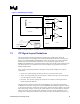
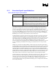
The most radical difference between the standard ITP700 and ITP700 Flex implementation
guidelines is the termination requirements for the BPM[5:0]# signals. For ITP700 Flex the
terminations on the debug port end of the transmission line are built into the ITP700 Flex device.
Note that this means that there is no termination on BPM[5:0]# if the ITP700 Flex is not installed.
If the platform designers require these signals to be terminated when ITP700 Flex is not installed it