
603 Pin Socket Design Guidelines


603 Pin Socket Design Guidelines
R
22
4.3.1. Design Procedure for Inductance Measurements:
The measurement equipment required to perform the validation is:
• Equipment - HP8753D Vector Network Analyzer or equivalent
• Robust Probe Station (GTL4040) or equivalent
• Probes - GS1250 & GSG1250 Air-Co-Planar or equivalent
• Calibration – Cascade Calibration Substrates or equivalent
• Measurement objects - Interposers, Sockets, Motherboards
Measurement Steps:
a) Equipment setup
1. Cables should be connected to the network analyzer and to the probes using the
appropriate torque wrench to ensure consistent data collection every time the
measurement is performed.
b) Set VNA
1. Bandwidth = 300KHz – 3GHz with 801 points
2. Averaging Factor = 16
c) Perform Open/Short/Load calibration
1. Calibration should be performed at the start of any measurement session.
2. Create Calibration Kit if necessary for 1
st
time
3. Do not perform port extension after calibration
d) Check to ensure calibration successfully performed
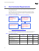
e) Measure the inductance of configuration 4 of the interposer mounted on the socket, which is
mounted to the motherboard fixture (Figure 4-5).
1. Call this
assemblysocket
L .
2. Export data into MDS/ADS or (capture data at frequency specified in item 6 of Table
4.1)
f) Measure the inductance of configuration 4 of the interposer mounted on the socket, which is
mounted to the motherboard fixture (Figure 4-5). Call this
sandwich
L .
1. Measure 30 units.
2. The interposer for 30 units must be chosen from different lots. Use 5 different lots, 6
units from each lot.
3. Export data into MDS/ADS or (capture data at frequency specified in item 6 of Table
4.1).