
ITP700 Debug Port Design Guide


R
ITP700 Debug Port Design Guide 63
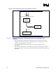
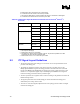
Figure 19 – ITP Clock Routing Options Using ITPCLKOUT[1:0] Pins
1K
ITP
Debug
Port
Intel®
Pentium
® 4
Processor
ITPCLKOUT[1:0]
33
33
BCLK[p/n]
ITPCLK[1:0]
NOTES:
1. There was an error in the WW41 Message of the Week (MOW) recommendation. The recommendation
stated to use individual matched
resistors to terminate ITPCLKOUT[1:0] when these signals are not in
use, to provide better immunity to ESD for processor inputs. Since these signals are outputs, a matched
(50-60 Ω) or 1 kΩ pull-up resistors this will not affect the ESD. However, using the matched resistors
will disable the option of using an ITP interposer. Please use the 1 kΩ pull-up resistors to ensure the
option of the ITP interposer solution.
2. For production boards, the 33 Ω pull-down resistor can be left unstuffed. Without the 33 Ω pull-downs,
the 1 kΩ pull-ups will effectively disable the ITPCLKOUT[1:0] for power savings and EMI reduction.