
Intel Xeon Processor Multiprocessor Platform Design Guide

82
Processor Power Distribution Guidelines
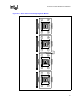
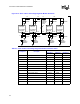
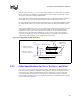
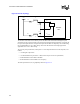
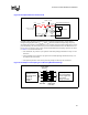
Figure 8-12. “Row” Pattern with Voltage Regulator Module Schematic
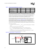
Table 8-5. “Row” Pattern with Voltage Regulator Module Schematic Values
Component Description
Values
Resistance Inductance Capacitance
OSCONs Bulk Capacitors 12 m
Ω / 5 3.1 nH / 5 5 × 560 µF
L1 VRM A – Proc A south 75
µΩ 20 pH -
L2 Proc A north - Proc B north 600
µΩ 160 pH -
L3 Proc A south - Proc B south 600
µΩ 160 pH -
L4 VRM B – Proc B south 75
µΩ 20 pH -
L5 Proc B north - sense 300
µΩ 80 pH -
L6 Proc B south - sense 300
µΩ 80 pH -
L7 Proc C north - sense 300
µΩ 80 pH -
L8 Proc C south - sense 300 µΩ 80 pH -
L9 VRM C – Proc C south 75
µΩ 20 pH -
L10 Proc C north - Proc D north 600 µΩ 160 pH -
L11 Proc C south - Proc D south 600
µΩ 160 pH -
L12 VRM D – Proc D south 75
µΩ 20 pH -
Voltage
Regulator
Remote
Sense
L1
Voltage
Regulator
Module A
OSCONs
L4
Voltage
Regulator
Module B
L5L2
L3 L11
L10
Proc B South
Side Input
Proc B North
Side Input
Proc A South
Side Input
Proc A North
Side Input
OSCONs
L9
Voltage
Regulator
Module C
Proc C South
Side Input
Proc C North
Side Input
L12
Voltage
Regulator
Module D
Proc D South
Side Input
Proc D North
Side Input
L6
OSCONs OSCONs OSCONs
OSCONs OSCONs OSCONs
L7
L8