
Intel Xeon Processor and Intel E7500/E7501Chipset Compatible Platform Design Guide

I/O Controller Hub 3 (Intel
®
ICH3-S)
154 Intel
®
Xeon™ Processor and Intel
®
E7500/E7501 Chipset Compatible Platform Design Guide
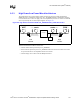
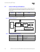
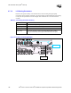
9.6.1 RTC External Circuit
The ICH3-S RTC module requires an external oscillating source of 32.768 kHz connected on the
RTCX1 and RTCX2 balls. Figure 9-11 documents the external circuitry that comprises the
oscillator of the ICH3-S RTC.
NOTES:
1. The exact capacitor values must be based on the crystal maker recommendation.
(Typical values for C1 and C2 are 18 pF for a crystal load of 12 pF.)
2. VCCRTC: Power for RTC Well
3. RTCX2: Feedback for the external crystal
4. RTCX1: Input to the internal oscillator
5. VBIAS: RTC BIAS Voltage – This pin is used to provide a reference voltage, and this DC voltage sets a
current, which is mirrored throughout the oscillator and buffer circuitry.
9.6.2 RTC External RTCRST# Circuit
The RTCRST# signal is used to reset the RTC well. The external capacitor and the external resistor
between RTCRST# and the RTC battery (VBAT) were selected to create an RC time delay, such
that RTCRST# will go high some time after the battery voltage is valid. The RC time delay should
be in the range of 10 ms – 20 ms. When RTCRST# is asserted, bit 2 (RTC_PWR_STS) in the
GEN_PMCON_3 (General PM Configuration 3) register is set to 1 and remains set until software
clears it. Because of this, when the system boots, the BIOS knows that the RTC battery has been
removed. Figure 9-11 is an example of RTCRST# circuitry that is used in conjunction with the
external diode circuit.
Figure 9-11. Example RTC External Circuitry
32.768 kHz
Xtal
C3
0.047 µF
VCCRTC
RTCX2
RTCX1
VBIAS
Vbatt
1 µF
3.3V Sus
C1
18 pF
C2
18 pF
R1
10 MΩ
R2
10 MΩ
RTCRST#
2.2 µF
8.2 kΩ
RTC External RTCRST# Circuit