
Dual Intel Xeon Processor Voltage Regulator Down (VRD) Design Guidelines

Dual Intel
®
Xeon™ Processor Voltage Regulator Down (VRD) Guidelines
15
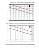
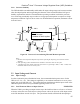
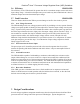
2.1.8 Converter Stability
The VRD should be unconditionally stable under all output voltage ranges and current transients
when developed against and incorporating the elements of the load model defined in Figure 2.
Stability requirements include a Thermal Monitor operating condition in which the processor
core clocks may periodically stop to reduce its average power dissipation in response to a high-
temperature condition. Figure 8 shows worst-case Thermal Monitor operation (maximum current
in the ON state).
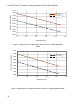
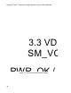
Notes:
1. Duration of on-off periods depends on processor speed: higher frequency processors have shorter
durations.
2. Other operating system-controlled events could have on-times as short as 700 cycles.
3. A possible worst-case routine could cause processor Icc to go through a 100% → 40% → 100% set of
transitions within 30-50 core clock cycles.
2.2 Input Voltage and Current
2.2.1 Input Voltages
In order to minimize power distribution losses, the recommended main power source for the
VRD is 12V +5%, -8%. This voltage is supplied by a conventional workstation or server power
supply such as the SSI EPS-12V. The system designer should ensure that the input circuit of the
VRD incorporates the necessary local bulk bypassing on the 12V rail.
2.2.2 Load Transient Effects on Input Current EXPECTED
When the VRD is providing an output current step to the load from Iout
MIN
to Iout
MAX
or Iout
MAX
to Iout
MIN
at the slew rate of 450A/µsec at the processor socket, the slew rate of the input current
to the VR should not exceed 0.5A/µsec. The system board needs sufficient bulk decoupling to
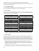
100%
40%
50%
5%
1
2
1
400
100%
40%
50%
5%
1
5-10
250
20
100% I
max
2.1 -
2.6 µs
2.2 -
2.7 µs
5% I
max
Units
• % of Icc-max
• number of clock cycles
Figure 10 – Processor Current during Thermal Monitor Operation