
Intel Xeon Processor with 800 MHz System Bus Thermal/Mechanical Design Guide

62 Intel® Xeon™ Processor with 800 MHz System Bus Thermal/Mechanical Design Guidelines
Test Setup Methodology
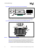
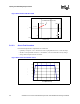
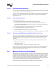
For active heatsinks, four thermocouples will be placed on the fan inlet as shown Figure B-23.
These thermocouples will be mounted between 5mm and 10mm above the fan. The average of
these measurements will be used to represent the local inlet temperature to the active heatsink.
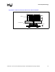
B.1.2.3 Processor Local Air Velocity
In the case where measurement of the local air velocity is desired, a single airflow probe will be
placed no closer than 10mm upstream of the processor heatsink. The probe will be centered with
respect to the cross-section of the heatsink and the tip perpendicular to the direction of flow (see
Figure B-24). The recommended air velocity probe can be used to measure both local air
temperature and air velocity. Utilizing the dual capability of the probe is highly recommended as
this minimizes the number of measurement devices that may disrupt flow to the processor heatsink.
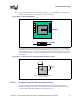
Figure B-22. Local Air Thermocouple Placement for Passive Heatsinks
T
a
Heatsin
k
X-Sect i onal View
T
LA
Heatsink
X-Sect i onal View
T
a
Heatsin
k
X-Sect i onal View
T
LA
T
a
Heatsin
k
X-Sect i onal View
T
LA
Heatsink
X-Sect i onal View
Figure B-23. Local Air Thermocouple Placement for Active Heatsinks (Side View)
T
a
Min. 5 mm
T
a
[.02”]
T T
LA LA
T
a
Min. 5 mm
T
a
[.02”]
T T
LA LA