
Intel Xeon Processor Multiprocessor Platform Design Guide

32
System Bus Routing
6.1 Return Path
The return path is the route current takes to return to its source. It may take a path through ground
planes, power planes, other signals, or integrated circuits. Determination of the return path is based
on electro-magnetic field effects. It is useful to think of the return path following a path of least
resistance nearest to the signal conductor. Discontinuities in the return path often have signal
integrity and timing effects that are similar to the discontinuities in the signal conductor. Therefore,
the return paths need to be given similar considerations. A simple way to evaluate return path
parasitic inductance is to draw a loop that traces the current from the driver through the signal
conductor to the receiver, and then back through the ground/power plane to the driver again. The
smaller the area of the loop, the lower the parasitic inductance will be.
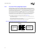
If via densities are large and most of the signals switch at the same time (as would be the case when
a whole data group switches layers), the layer to layer bypass fails to provide an acceptably short
signal return path to maintain timing and noise margins. Experience at Intel indicates that the
magnitude of the uncertainty that occurs with shifting return paths is on the same order as the data
bus cycle time. Since the signals are routed using symmetric stripline, return current is present on
both the V
CC
and V
SS
planes. If a layer change must occur, then V
CC
and V
SS
vias must be placed
as close to the signal via as possible to provide the shortest possible path for the return current.
The following sets of return path rules apply to all designs:
• Always trace out the return current path and provide as much care to the return path as the path
of the signal conductor.
• Do not allow splits in the reference planes in the path of the return current.
• Do not allow routing of signals on the reference planes near system bus signals.
• Do not make signal layer changes that force the return path to make a reference plane change
even if it is from one V
SS
layer to another V
SS
layer.
• Decoupling capacitors do not adequately compensate for a plane split.
• Do not route over via anti-pads or socket anti-pads
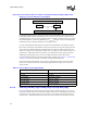
If reference plane changes must be made:
• Change from a V
SS
reference plane to a V
SS
reference plane and place a via connecting the
two planes as close as possible to the signal via. This also applies when making a reference
plane change from on V
CC
plane to another V
CC
plane.
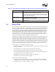
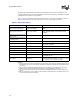
Parameter 4-Way: Intel® Xeon™ Processor MP
Reference plane requirements Signals should be routed in a symmetric stripline configuration.
Avoid changing layers when routing system bus signals.
If a layer change must occur, use vias connecting the V
CC
planes and/or V
SS
planes to provide a low impedance path for the return current. Vias should be
as close as possible to the signal via.
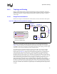
Serpentine spacing S/H ratio greater than or equal to 5 (Figure 6-1)
Keep parallel sections as short as possible
Minimize 90-degree bends, use 45-degree bends whenever possible
Motherboard Impedance 47 Ω–50 Ω ± 10%
Table 6-1. System Bus Routing Summary for 4-Way Processor Configurations (Sheet 2 of 2)