
Intel Xeon Processor Multiprocessor Platform Design Guide

103
Methodology for Determining Topology and Routing Guidelines
9.2.5.3 Incorporating Package Effects into the Flight Time
Flight time should be simulated beginning and ending at the pad of the silicon, not at the package
pin. This allows the skew due to the package trace length differences to be accounted for.
Additionally, the traces on the motherboard should be skewed appropriately to cancel any skews
built into the package.
9.2.6 Parameter Sweeps and Monte Carlo Analysis
This part of the sensitivity analysis constitutes the bulk of the pre-route design. In this section of
the design phase, all system variables shown in Table 9-1 are varied, and the solution space for the
design is determined.
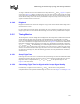
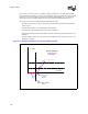
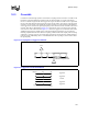
Figure 9-9. Traditional Method of Calculating Flight Time Assuming a Nonlinear Edge from V
IL
Through V
IH
at the Receiver
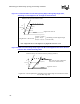
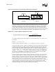
Figure 9-10. Traditional Method of Calculating Flight Time Assuming a Ringback Violation
from V
IL
Through V
IH
at the Receiver
Extrapolate the
Vih
crossing at the minimum
edge rate back to the switching threshold
Vih
Threshold
Vil
Ta
Tb(extrapolated)
Flight Time = Tb ( extrapolated)- Ta
Reference driver into reference load
Signal at
at receiver
(Assuming a non-linear edge through
Vil
and
Vih
)
min edge rate
Extrapolate the Vih crossing at the
maximum edge rate back to the
switching threshold
Vih
Threshold
Vil
Ta
Tb(extrapolated)
Flight Time = Tb(extrapolated)-Ta
Reference driver into reference load
Signal at at receiver
(Assuming a non-linear edge through Vil and Vih)
Max edge rate