
Intel Xeon processor LV Thermal Design Guide

Reference Thermal Solutions
Dual-Core Intel
®
Xeon
®
processor LV and ULV
Thermal Design Guide August 2006
30 Reference Number: 311374-002
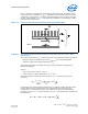
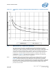
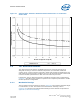
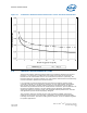
It is important to realize that the thermal interface material degrades over time and
exposure to environmental effects. Figure 13, Figure 15, and Figure 17 show the
junction-to-ambient thermal performance assuming the “end of life” performance for
the reference TIM. End of life usually occurs in to 5 to 7 years. Actual test data may
differ from the values shown since the TIM thermal resistance will be comparable to the
“beginning of life” impedance. It is common for the TIM impedance to increase
significantly over time (i.e., > 2x). The end user must ensure that they account for the
TIM thermal performance over the expected lifetime of the computing system.
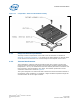
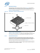
6.6 Heatsink Orientation
All of the heatsinks were designed to maximize the available space within the
volumetric keep-out zone and their respective form factor limitations. These heatsinks
must be oriented in a specific direction relative to the processor keep-out zone and
airflow. In order to use these designs, the processor must be placed on the PCB in an
orientation so the heatsink fins will be parallel to the airflow. Figure 18 illustrates this
orientation.
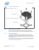
6.7 Dual Processor Considerations
The heatsink designs presented are suitable for use in dual-processor configurations.
However additional precautions must be taken with the orientation of the processors on
the motherboard. The results of computer modeling and testing indicate that
processors placed in series, that is one processor placed directly behind the other
relative to the airflow, will have a higher CPU temperature when compared to
processors placed in parallel (side-by-side relative to the airflow). As a result, it is
strongly recommended that the processors be placed in the parallel configuration for
optimized thermal performance. For a better understanding, Figure 18 illustrates the
preferred configuration.