
Intel Xeon Processor and Intel E7500/E7501Chipset Compatible Platform Design Guide


Intel
®
Xeon™ Processor and Intel
®
E7500/E7501 Chipset Compatible Platform Design Guide 67
System Bus Routing Guidelines
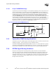
5.2.3 BR[3:0]# Routing Guidelines
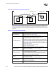
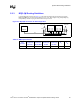
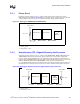
Connect BR[3:0]# as shown in Figure 5-3. The total bus length must be less than 20.2 inches.
BR3# and BR2# are not used and are pulled to VCC_CPU. The designer may pull-up BR[3:2]
independantly instead of tying the lines between the processors.
Figure 5-3. BR[3:0]# Connection for DP Configuration
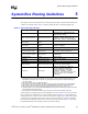
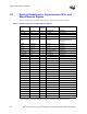
Table 5-6. BR[3:0]# Connection
Trace
Impedance
L1
Processor-to-
Processor
L2
Processor1
BR1# to MCH
L3
Processor-to-
R
T
Stub
L4
Processor-to-
R
PU
Stub
R
T
R
PU
50 Ω 3.0 – 10.0” 15.7” max 1” max 3” max 50 Ω ± 5% 50 Ω ± 5%
MCH
Processor 1
BR0#
BR1#
BR2#
BR3#
BR0#
BR1#
BR2#
BR3#
VCC_CPU
Rpu
Processor 0
L1
L2
L4
VCC_CPU
BREQ0#
R
T
RT
RT
L3
L3
L3