
Intel Xeon Processor and Intel E7500/E7501Chipset Compatible Platform Design Guide

Platform Power Delivery Guidelines
192 Intel
®
Xeon™ Processor and Intel
®
E7500/E7501 Chipset Compatible Platform Design Guide
11.2.9.2 Bulk Decoupling
The Intel Xeon processor causes very large switching transients. These sharp surges of current
occur at the transition between low-power mode and high-power mode. The designer must support
a current slew rate of 450 A/µs at the socket pins.
Load-change transients for the Intel Xeon processor are on the order of 55 A. A load-change
transient occurs when coming out of or entering a low-power mode. These are not only quick
changes in current demand, but also long lasting average current requirements. This occurs when
the STPCLK# pin is asserted or de-asserted, and during Auto HALT. Auto HALT is a low power
state the processor enters by issuing a HALT instruction, and a HALT bus cycle is generated.
Note: Note that even during normal operation (not STPCLK# or Halt), the processor current
requirements can change by as much as 70% (± 10%) of the max current very quickly.
Table 11-5 lists the recommended bulk capacitance parameters for Intel Xeon processors. The
following recommendations indicate the decoupling suggested for each processor in the system.
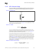
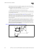
Place some bulk decoupling on the baseboard as close to the processor socket as possible
(maximum of 0.5 inch away). The location of bulk capacitance is not as critical as the high-
frequency decoupling because more inductance is already expected for these components.
However, good placement of these components will affect the transient response of the system for
the better, as shown in simulation. Place the remaining bulk capacitors next to the voltage converter
module.
Place half on one side of the processor socket, half on the other side as close as the logic analyzer
interface (LAI), retention mechanism (RM) and heatsink keep-out zones allow. Capacitors should
be placed a maximum of 0.5 inch from the processor socket. Check with your LAI, RM and
heatsink vendors for those keep-out zone requirements. When using the Intel Xeon processor
boxed processor solution, refer to the
Intel
®
Xeon™ Processor Datasheet for keep-out zone
details.
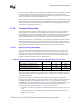
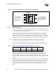
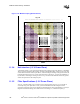
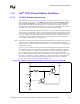
Figure 11-16. Decoupling Example for a Microstrip Baseboard Design
3-4 0.1 uF with 0805
body over the address
and control signals and
as close to the processor
package as possible.
4-6 0.1 uF with 0805
body over the data
signals and as close
to the processor
package as possible.
Data Pins
Address and
Control Pins
Cavity Under
Processor
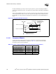
Table 11-5. Processor Bulk Capacitance Recommendation Per Processor
Bulk Capacitance Quantity ESR ESL
RMS Current
Rating
OS-CON, 560 µF 10 12 mΩ 3.1 nH Max 5.04 Arms