
Intel Xeon Processor Multiprocessor Platform Design Guide


94
Methodology for Determining Topology and Routing Guidelines
9.1.1.2 Hold Time
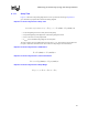
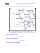
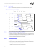
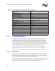
The hold timing diagram for a source synchronous bus design is shown in Figure 9-3. The total
loop equation is derived from the hold timing diagram.
Equation 9-5. Source Synchronous Loop Equation for Hold Timing Diagram
• T
co
(strobe)[(data)] is the driver delay of the strobe [data]
• T
flight
(strobe)[(data)] is the flight time of the strobe [data] interconnect
• T
hold
is the receiver's hold time requirement
• T
margin
is the available timing margin for the hold time
The loop equation can be simplified and solved for T
margin_hold
. The equation can be broken into
two parts, valid before and interconnect skew. Then, the hold margin can be determined.
Equation 9-6. Source Synchronous, Valid After
Equation 9-7. Source Synchronous, Interconnect Skew
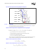
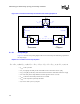
Figure 9-2. Source Synchronous Timing Diagram for Setup Time
(data)
CLK
DATA
DRIVER
STROBE
STROBE
RECEIVER
RECEIVER
STROBE
STROBE
DRIVER
DRIVER
DATARECEIVER
T
setup
T
flight
T
co
(strobe)
T
flight
(strobe)
T
co
(data)
T
margin
0)()()()(
_arg
=−−−−+ strobeTstrobeTTTdataTdataT
coflightholdholdinmflightco
minmax
)()( strobeTdataTT
cocovb
−=
minmaxmax,
)()( strobeTdataTT
flightflightskew
−=