
Intel Xeon processor LV Thermal Design Guide

Dual-Core Intel
®
Xeon
®
processor LV and ULV
August 2006 Thermal Design Guide
311374-002
3
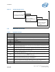
Contents
1.0 Introduction..............................................................................................................6
1.1 Design Flow........................................................................................................6
1.2 Definition of Terms..............................................................................................7
1.3 Reference Documents..........................................................................................8
1.4 Thermal Model Availability....................................................................................8
2.0 Package Information.................................................................................................9
3.0 Thermal Specifications ............................................................................................16
3.1 Thermal Design Power .......................................................................................16
3.2 Maximum Allowed Component Temperature..........................................................16
4.0 Mechanical Specifications........................................................................................17
4.1 Package Mechanical Requirements.......................................................................17
4.2 Package Keep-Out Zones Requirements ...............................................................17
4.3 Board Level Keep-Out Zone Requirements............................................................17
5.0 Thermal Solution Requirements...............................................................................20
5.1 Characterizing the Thermal Solution Requirement..................................................20
6.0 Reference Thermal Solutions...................................................................................23
6.1 AdvancedTCA* Reference Heatsink......................................................................23
6.1.1 Mechanical Design..................................................................................23
6.1.2 Keep-Out Zone Requirements ..................................................................24
6.1.3 Thermal Performance..............................................................................24
6.2 1U+ Reference Heatsink.....................................................................................25
6.2.1 Mechanical Design..................................................................................25
6.2.2 Keep-Out Zone Requirements ..................................................................26
6.2.3 Thermal Performance..............................................................................26
6.3 Thermal Interface Material (TIM).........................................................................27
6.4 Heatsink Orientation..........................................................................................28
7.0 Thermal Metrology ..................................................................................................29
7.1 Heatsink Validation Using Thermal Test Vehicles....................................................29
7.2 Die Temperature Measurements..........................................................................29
7.3 Power Simulation Software.................................................................................29
7.4 Additional Thermal Features ...............................................................................29
8.0 Reliability Guidelines...............................................................................................30
A Thermal Modeling Tools...........................................................................................31
A.1 Recommended Thermal Modeling Method .............................................................31
A.2 Example Estimating Ψ
JA
Using Thermal Models.....................................................32
B Thermal Solution Component
Suppliers .................................................................................................................35
B.1 Reference Heatsink............................................................................................35
C Mechanical Drawings...............................................................................................36
Figures
1 Thermal Design Process..............................................................................................7
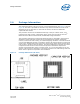
2 Package Dimensions (3D View)....................................................................................9
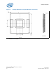
3 Package Dimensions (Top and Side View: One of Two)..................................................10
4 Package Dimensions (Bottom View: One of Two)..........................................................11