
Intel Xeon Processor and Intel E7500/E7501Chipset Compatible Platform Design Guide


Intel
®
Xeon™ Processor and Intel
®
E7500/E7501 Chipset Compatible Platform Design Guide 189
Platform Power Delivery Guidelines
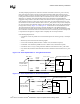
To satisfy damping requirements, total series resistance in the filter (from VCC_CPU to the top
plate of the capacitor) must be at least 0.35
Ω. This includes the DCR of the inductor and any
resistance (routing or discrete components) between VCC_CPU and capacitor top plate. Keep the
routing short and wide. If the total is less than 0.35
Ω, add a discrete resistor to make up the
difference. For example, if the selected filter inductor has a minimum of 0.1
Ω DCR and a
negligible routing resistance (less than 10 m
Ω), add a discrete resistor of approximately 0.3 Ω. The
total maximum resistance in each route cannot be more than 1.1
Ω as measured from VCC_CPU
(the baseboard via that connects the PLL filter to the VCC_CPU plane) to the processor interposer
pin. It is important to keep the total resistance of each of the PLL filter circuits on the motherboard
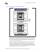
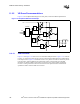
no larger than necessary. Figure 11-14 and Figure 11-15 illustrate the recommended filter circuit.
This path includes the total trace resistance (denoted “R-TRACE” in the following figures),
discrete resistor (if needed), inductor DCR, and Socket resistance ( 0.025
Ω). It is important to note
that “R-TRACE” includes the total trace resistance between VCC and the processor socket pin, but
is represented in the figures as a single resistor to simplify the circuit representation.
Other Routing Requirements:
• C should be as close as possible to VCCA and VSSA pins in the socket (typically < 0.02 Ω per
route).
• Route away from clocks and fast switching signals.
• VCCA route should be parallel and next to VSSA route (to minimize loop area).
• VCCIOPLL route should be parallel and next to VSSA route (to minimize loop area).
• L should be close to C; any routing resistance should be inserted between VCC_CPU and L.
• Any discrete R (if needed to meet minimum resistance) should be inserted between VCC_CPU
and L.
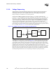
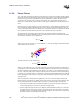
Figure 11-14. Filter Implementation 1: Using Discrete Resistor
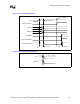
Figure 11-15. Filter Implementation 2: No Discrete Resistor
VCC_CPU
VCCA
VSSA
VCCIOPLL
L
C
C
Processor
PLL
R-Trace
Processor Interposer "Pin"
Trace < 0.02 Ω
Socket Pin
Baseboard Via that
Connects Filter to
VCC_CPU Plane
R-Socket
R-Socket
R-Socket
Discrete
Resistor
R-Trace
Discrete
Resistor
L
VCC_CPU
VCCA
VSSA
VCCIOPLL
L
C
C
Processor
PLL
R-Trace
Processor Interposer "Pin"
Trace < 0.02 Ω
Socket Pin
Baseboard Via that
Connects Filter to
VCC_CPU Plane
R-Socket
R-Socket
R-Socket
R-Trace
L